A measurement method of double cameras solid vision based on dot structure light system
2014-05-13 10:02:52QIAONaoShengZHANGFen
湖南文理學(xué)院學(xué)報(自然科學(xué)版) 2014年2期
QIAO NaoSheng, ZHANG Fen
?
A measurement method of double cameras solid vision based on dot structure light system
QIAO NaoSheng1, ZHANG Fen2
(1. School of Physics and Electronics, Hunan University of Arts and Science, Changde 415000, China; 2. School of Computer Science and Technology, Hunan University of Arts and Science, Changde 415000, China)
This paper proposes a measurement method of double cameras solid vision based on dot structure light system. Firstly, the basic principle is described in detail, the simple physical explain is given, the relation between the coordinates of imaging dot of double cameras and that of testing dots are deduced, the transform matrix of measurement system constituted by double cameras is obtained, the method of deciding energy center of each testing dot on the calibration board is proposed. Secondly, corresponding error estimation method is proposed. Finally, the results of measurement experiment are given which show that its value of measurement error is very small.
vision measurement, double cameras, dot structure light system, error estimation method
Double cameras solid vision is an important composition of computer vision, and it is an important study content in computer vision when I use it to measure solid object. The presupposition and foundation of acquiring solid space information by using double cameras solid vision is camera system calibration, and the course of calibration is mainly to decide the internal and external parameters of cameras.
Nowadays there are many methods of vision measurement based on double cameras[1—11]. For example, Tsai R Y[1—2]proposed that he can use the two-step method to obtain internal and external parameters of cameras, and the experiment condition and request are not high. Aiming at usual camera model with one step radial distortion, Zhang Y Z[3]proposed a calibration method to obtain the parameters of cameras by resolving linear equations. To overcome the shortcomings of traditional measurement methods for faulting detection on the cement concrete pavement, Ying H[4]proposed a new measurement method for faulting detection. Aiming at the shortcoming of existing reflector calibration approach, Chi J N[5]proposed a system calibration approach based on global calibration of double cameras. In order to solve the problem that cameras can not directly measure the object spatial coordinates outside field of view outside, Zhang Q[6]proposed a system calibration method based on plane mirror.
This paper proposes a measurement method of double cameras solid vision based on dot structure light system. And its basic principle is given, the process of system calibration is deduced, corresponding error estimation method is proposed, ideal experiment result is obtained.
1 Basic principle
In the dot structure light system, the double cameras solid vision optical configuration is shown in Fig. 1. Supposing the coordinates system is,(,,) denotes solid coordinates dot of testing dot.1(1,1) denotes ideal imaging plane coordinates dot of testing dotin the first camera, and1denotes lens center of the first camera.2(2,2) denotes ideal imaging plane coordinates dot of testing dotin the second camera, and2denotes lens center of the second camera.
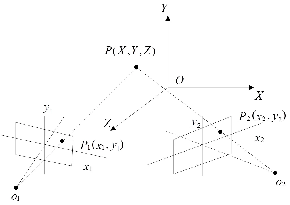
Fig.1 Double cameras solid vision optical configuration in the dot structure light system
There is such transform relation between the imaging dot coordinates and the testing dot coordinates in the first camera
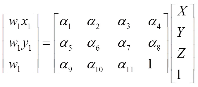
where1is the parameter whose value is unequal to zero, and1,1,…,11are the elements of system transform matrix which are related with the aspects between the location position of the first camera and the parameters of imaging system I.
And there is such transform relation between the imaging dot coordinates and the testing dot coordinates in the second camera

where2is the parameter whose value is unequal to zero too, and1,2,…,11are the elements of system transform matrix which are relation to the aspects between the location position of the second camera and the parameters of imaging system II.
It can be seen from Eqs (1) and (2) that it has unknown parameters whose number is 22 inaandb, and it can obtain linear equations whose number is 4 when I use one known testing dot and its two imaging dots being located at corresponding two imaging surface of cameras. Supposing these unknown parameters whose number is 22 must be obtained, these known testing dots whose number is 6 at least must be known. And I can obtain these parameters according to Eqs(1) and (2), i.e, I can obtain transform matrixandof measurement system of double cameras, and that is system calibration as we all know.
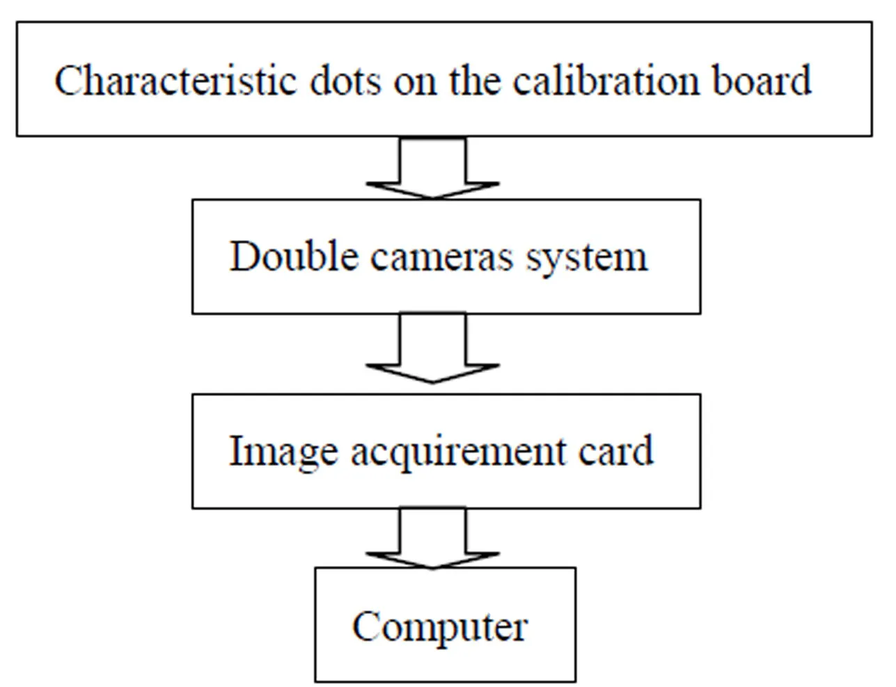
Fig.2 The process of system calibration
The process of system calibration is shown in Fig.2. In actual, each testing dot in the calibration board is some small bright marks with high reflection rate, because they may directly affect measurement accuracy, it must execute image processing after imaging through cameras to decide its coordinates of center accurately. It has many methods to decide the coordinates of center dot. Our method includes two steps. Firstly, the outline edge of image marks of testing dots must be found. Secondly, the energy center of image marks of testing dots must be decided. And their coordinates (,) can be expressed as:
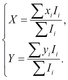
where (x,y) is coordinates location of the pixel of corresponding image after projection again,Iis gray value of the pixel in such location.
When the coordinates of characteristic dots on the calibration board and the coordinates of corresponding imaging dots situated at the imaging place of two cameras are substituted in Eqs(1) and (2), then transform matrix of two imaging system can be decided, i.e, the system calibration can be finished.
2 Error estimation method
We adopt the absolute error value and relative error value of image coordinate of testing dot captured by cameras to evaluate error, and its process is described as follows:
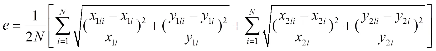
Supposing (1li,1li) is coordinates location of real image of testing dot in the first camera, and (1i,1i) is coordinates location of corresponding image after projection again. The rest may be deduced by analogy, (2li,2li)and (2i,2i) are corresponding coordinates location in the second camera.
Aiming at testing dots whose number is, the absolute error value of testing dotcan be expressed as:

The relative error value of testing dot P can be expressed as:
3 Results of experiment
We adopt the experiment data of literature[7]as demarcation image, and its resolving power is 640 × 480, character dots are each foursquare vertex whose number is 256, and half of which is demarcation dot, another half is testing dot.
We have obtained better experiment results. The maximum value of absolute error of image coordinate of testing dotismax= 0.292 6 pixels, the corresponding average value ismean= 0.198 2 pixels. And the maximum value of relative error of image coordinate of testing dotismax= 0.18%, the corresponding average value ismean= 0.15%. It is obvious that the absolute error value is less and under 0.3 pixels, the relative error is also less and under 0.2 %. So the precision is very high.
[1] Lenz P K, Tsai R Y. Techniques for calibration of the scale factor and image center for high accuracy 3-D machine vision metrology [J]. IEEE Transactions on Pattern Analysis and Machine Intelligence, 1988, 10(5): 713—720.
[2] Tsai R Y. A versatile camera calibration technique for high-accuracy 3D machine vision metrology using off-the-shelf TV cameras and lenses [J]. IEEE Journal of Robotics and Automation, 1987, 3(4): 323—344.
[3] Zhang Y Z, Ou Z Y. A new linear approach for camera calibration [J]. Journal of Image and Graphics, 2001, 6A: 727— 731.
[4] Ying H, Tan Z M. Cement concrete pavement faulting detection and recognization based on binocular vision [J]. Journal of Tongji University: Natural Science, 2011, 39: 247—252.
[5] Chi J N, Zhang C, Wang C J, et al. Calibation for gaze tracking system of binocular vision and double infrared light source [J]. Chinese Journal of Scientific Instrument, 2011, 32: 883—891.
[6] Zhang Q, Wang Z L, Chi J N, et al. Calibration for gaze tracking system based on stereo cameras and plane mirror [J]. Acta Optica Sinica, 2011, 31(4): 0415002/1-0415002/7.
[7] Zhang Z Y. A flexible new technique for camera calibration [J]. IEEE Transactions on Pattern Analysis and Machine Intelligence, 2000, 22(11): 1330—1334.
[8] Shi S W, Liu J. A novel approach to 3-D gaze tracking using stereo cameras [J]. IEEE Transactions on System Man and Cybernetics Syst Man Cybernetics Part B Cybernetics, 2004, 34(1): 234—245.
[9] Xu H H, Li X F, Zuo D W, et al. Double-CCD stereoscopic vision system monitoring chip shape [J]. Key Engineering Materials, 2006, 315-316: 66—70.
[10] Bagaria V, Nagesh A S, Varun A V. Double aperture camera for high resolution measurement [J]. Engineering and Technology, 2009, 59: 423—427.
[11] Katahara S, Aoki M. Vehicle detection using double slit camera[A]. Proceedings of 7th Asian Conference on Computer Vision[C]. Hyderabad, India, 2006, 3852: 162—170.
基于點結(jié)構(gòu)光系統(tǒng)雙攝像機(jī)立體視覺測量方法
喬鬧生1, 張 奮*2
(1. 湖南文理學(xué)院 物理與電子科學(xué)學(xué)院, 湖南 常德, 415000; 2. 湖南文理學(xué)院 計算機(jī)科學(xué)與技術(shù)學(xué)院, 湖南 常德, 415000)
提出了一種基于點結(jié)構(gòu)光系統(tǒng)的雙攝像機(jī)立體視覺測量方法. 首先詳細(xì)闡述了其基本原理, 給出了簡單的物理解釋, 推導(dǎo)出了雙攝像機(jī)像點坐標(biāo)與測試點坐標(biāo)之間的關(guān)系, 求出了雙攝像機(jī)組成的測量系統(tǒng)的變換矩陣, 提出了確定靶標(biāo)上各測試點能量中心的辦法. 然后提出了相應(yīng)的誤差評估方法. 最后給出了實驗測量結(jié)果, 結(jié)果表明測量誤差較小.
視覺測量; 雙攝像機(jī); 點結(jié)構(gòu)光系統(tǒng); 誤差評估方法
O 439
1672-6146(2014)02-0022-04
10.3969/j.issn.1672-6146.2014.02.005
通訊作者email:190138413@qq.com.
email: naoshengqiao@163.com.
2014-05-06
湖南省教育廳重點項目(13A062); 湖南省科技廳科研項目(2014FJ3027, 2011FJ3076); 光電信息集成與光學(xué)制造技術(shù)湖南省重點實驗室項目; 湖南文理學(xué)院重點建設(shè)項目(光學(xué)); 光電信息技術(shù)校企聯(lián)合人才培養(yǎng)基地; 中國博士后科研基金(2012M521553).
(責(zé)任編校:劉剛毅)
猜你喜歡
機(jī)電信息(2023年24期)2023-12-26 10:55:38
軍民兩用技術(shù)與產(chǎn)品(2022年1期)2022-06-01 06:28:50
連云港文學(xué)(2021年2期)2021-07-25 02:04:40
音樂教育與創(chuàng)作(2020年12期)2020-12-25 06:49:32
科技進(jìn)步與對策(2020年19期)2020-10-15 02:33:22
大眾文藝(2020年15期)2020-09-11 02:28:04
上海大學(xué)學(xué)報(自然科學(xué)版)(2020年4期)2020-05-24 07:29:38
連云港文學(xué)(2020年6期)2020-03-17 01:40:06
大眾文藝(2019年23期)2019-12-15 09:59:08
音樂教育與創(chuàng)作(2019年5期)2019-11-14 01:13:28