
A novel low-loss four-bit bandpass filter using RF MEMS switches
2022-01-23 06:35:18LuluHan韓路路YuWang王宇QiannanWu吳倩楠ShiyiZhang張世義
Chinese Physics B 2022年1期
關(guān)鍵詞:王宇
Lulu Han(韓路路) Yu Wang(王宇) Qiannan Wu(吳倩楠) Shiyi Zhang(張世義)
Shanshan Wang(王姍姍)1,2,3,4, and Mengwei Li(李孟委)1,2,3,4,?
1School of Instrument and Electronics,North University of China,Taiyuan 030051,China
2Nantong Institute of Intelligent Opto-Mechatronics,North University of China,Nantong 226000,China
3Center for Microsystem Integration,North University of China,Taiyuan 030051,China
4Academy for Advanced Interdisciplinary Research,North University of China,Taiyuan 030051,China
5School of Science,North University of China,Taiyuan 030051,China
Keywords: four-bit,RF microelectromechanical system(MEMS)switch,reconfigurable filter,comb resonator
1. Introduction
Bandpass filters are widely used in microwave and millimeter-wave circuits and systems due to their ability to select or suppress signals at specific frequencies.[1-12]In recent years,great attention has been paid to reconfigurable filters based on various circuit structures,owning to their ability to reduce complexity and strengthen expansibility in modern electronic systems.[13-19]
Traditional reconfigurable filters, including semiconductor filters,[14]and MEMS filters,[15-17,19]have been extensively studied over the last two decades. However, these filters have shortcomings,such as large structural size,complex structure, high loss, and low integration. Chuanget al.[14]proposed a switchable filter with a selectable range of 0.9-2.35 GHz based on the use of p-i-n diode switches. The maximum insertion loss of the filter was approximately 3 dB,and the overall size was 97 mm×32 mm. Since each diode was too complicated to be integrated into a uniplanar filter structure,this reconfigurable bandpass filter had limitations,for instance, a large size and large insertion loss. Moreover, based on MEMS switches, Zhanget al.[15]demonstrated an openloop reconfigurable filter composed of“open-loop”resonators and cantilever MEMS switches with reconfigurable frequency bands of 7.81 GHz and 8.35 GHz,respectively. The insertion loss of this reconfigurable filter in the passband was smaller than 3.4 dB,and its size was 25 mm×17 mm. Compared with the device described in Ref.[14],its size was greatly reduced,but it was still not conductive to integration into an RF module.
To address the abovementioned problems associated with existing MEMS reconfigurable filters, this study proposes a novel low-loss four-bit filter using RF MEMS switches. It can switch 16 operating states through eight switches in the frequency range of 7-16 GHz, and the overall size of this novel proposed filter is only 4.4 mm×2.5 mm×0.4 mm. It can effectively reduce insertion loss, reduce the system size, and improve the reliability of the system.
2. Theory and design
2.1. Design of the MEMS switch
The reconfigurable filter has eight MEMS switches that represent 16 operating states according to their positioning in the ‘up’ and ‘down’ states. Ohmic contact MEMS switches are employed to tune the filter frequency,[20,21]the equivalent circuit diagram is shown in Fig.1,in whichZcpwis the equivalent impedance of a coplanar waveguide (CPW),Rsis the resistance when the switch is“closed”,andCsis the coupling capacitance formed by the cantilever beam and the CPW signal line when the switch is“open”.
The cantilever beam of the MEMS switch is a straight plate structure that has the characteristics of a simple structure and is easy to process. Additionally, to facilitate the release of the sacrificial layer and reduce the driving voltage of the MEMS switch, several release holes are designed in the cantilever beam. The structure and simulation results of the MEMS switch are shown in Figs.2(a)and 2(b),respectively.
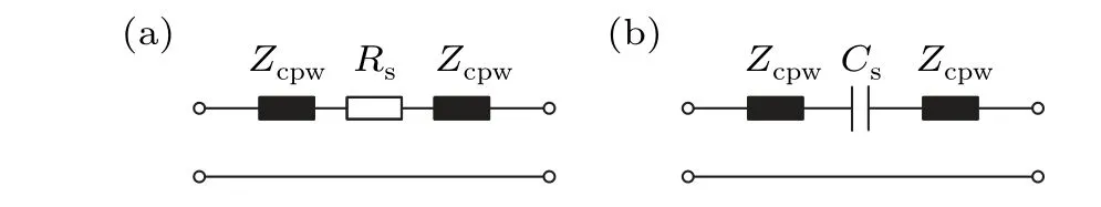
Fig. 1. Equivalent circuit diagram of the ohmic contact MEMS switch: (a)“closed”state and(b)“open”state.
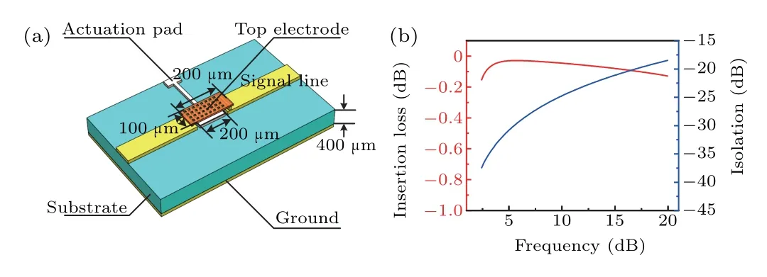
Fig. 2. (a) Structure of the MEMS switch. (b) Simulation results of the MEMS switch.
The elastic coefficient of the straight plate cantilever beam design is mainly determined by the beam stiffness,k.When the driving voltage is applied directly under the cantilever beam,it is equivalent to a distributed load acting on the single-ended cantilever beam. Based on this,the elastic coefficientkof the cantilever beam can be expressed as
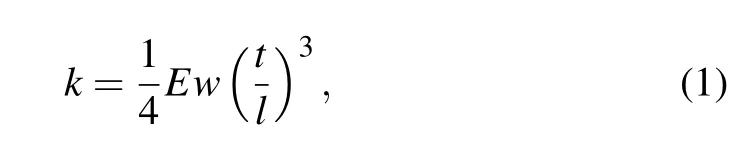
wherel,w,t, andEare the length, width, thickness, and Young’s modulus of the cantilever beam. The elastic coefficient,kc, of the designed cantilever beam is calculated to be 1.024 N/m. The area between the cantilever beam and the pull-down electrode isA=18000 μm2, and the distance between the cantilever beam and the pull-down electrode isg=3.0μm. According to the calculation,the driving voltage isV=12.41 V.
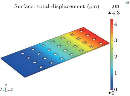
Fig.3. Displacement simulation of the cantilever beam of the MEMS switch.
The coupling field finite-element software,COMSOL,is used to simulate the cantilever beam of the MEMS switch,and the simulation results are shown in Fig.3.The cantilever beam deforms under the action of static electricity,and the deformation is largest at its free end.When a distributed load is applied directly under the cantilever beam, the maximum displacement of the cantilever beam in theZdirection is 4.3μm,which is greater than the distance of 3.0μm between the switch pulldown electrode and the cantilever beam. We have therefore determined that the structure of the designed switch is reasonable.
2.2. Design of the comb resonator
In this study,a stepped impedance resonator(SIR)is applied to the comb resonator to realize the design of a miniaturized filter. SIRs are divided into theλg/4 type,theλg/2 type,and theλgtype. Theλg/4 type of SIR is selected because of its small size and the location of the center of its second passband at triple the base frequency. Theλg/4 type SIR is composed of an open circuit and short circuit in series through an impedance step junction.As shown in Fig.4,the equivalent impedance and equivalent electrical length of the open-circuit end are(Z1,θ1),and the equivalent impedance and equivalent electrical length of the short-circuit end are (Z2,θ2), respectively.
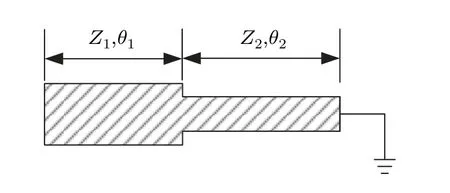
Fig.4. Schematic of a λg/4-type SIR.
Equation (2) represents the input impedance, ignoring the edge capacitance of the resonator. If the admittance isYi=1/Zi=0,theλg/4-type SIR resonance condition can be achieved as shown in Eq. (3). Thus, theλg/4-type SIR resonance conditions are related toθ1,θ2,andZ1/Z2.

Equation (4) represents the total electrical length of theλg/4-type SIR. Compared with the electrical length ofπ/2 of a uniform impedance resonator (whose open-end width is equal to the short-end width), the SIR normalized resonator length is

The comb resonator is composed of an arrangement of parallel coupling lines,in which one end is short-circuited and the other end is grounded through the lumped capacitor. Two symmetrical 50 Ω transmission lines are arranged at both ends of the resonator to form input and output signal ends of the resonator.[22]
In the schematic diagram of the comb resonator in Fig.5,C′irepresents the load capacitance corresponding to the coupling line in sectioni, whereW′irepresents the width of the coupling line in sectioni,L′irepresents the length of the coupling line in sectioni, andSi,i+1represents the interval between the coupling line in sectioniand sectioni+1 of the resonator. Here,i=0-m. For narrowband comb resonators,the coupling lines from sections one tomare all resonators.The coupling lines of section zero and sectionm+1 feed the external circuit, which changes the impedance instead of acting as a resonator.[23]
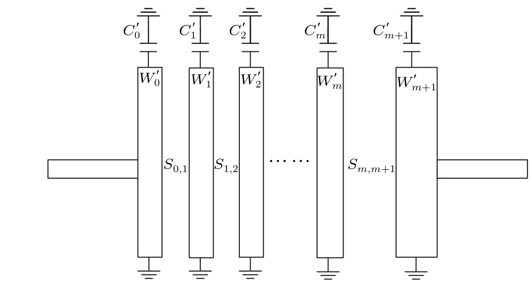
Fig.5. Schematic diagram of the comb resonator.
Comb resonators have evolved from parallel coupling line resonators,and the central frequency of the resonator is mainly determined by the length of the resonator and the load capacitance. The coupling coefficient and the port loadQvalue of the resonator can be calculated by[24]

whereσiis the Chebyshev low-pass prototype value,f0is the center frequency of the filter,BWis the passband bandwidth of the filter,and theKlevel is the coupling coefficient.
2.3. Design of the four-bit filter
Generally,the terminal load capacitance of the comb line is small and fixed. The central frequency of the filter can be adjusted by changing the capacitance if the fixed capacitance is replaced by an adjustable capacitor. Equation(7)shows the relationship between the central frequency of the filter,the resonator length,and the terminal capacitance value:
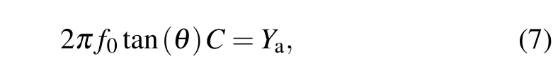
whereYais the characteristic admittance of the resonator,θis the electrical length of the resonator, andCis the terminal capacitance.
According to Eq.(7),the inverse relationship between the resonance frequency and the capacitance can be obtained by fixing the electrical length of the resonator and the specific admittance.Based on this characteristic,we designed a reconfigurable bandpass filter. The designed reconfigurable filter consists of eight MEMS switches and comb resonators,and the selection of a specific operating frequency band can be achieved by controlling the gating state of the MEMS switches.
The reconfigurable filter in Fig. 6 is manufactured using MEMS technology and is mainly composed of a substrate and a metal structure.
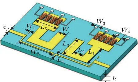
Fig.6. The structure of the reconfigurable filter.
The filter uses a microstrip line to transmit microwave signals, and the characteristic impedance of its input/output terminals is 50 Ω. By controlling the size of each comb resonator and optimizing the spacing between them,a filter with excellent performance can be obtained. The structural parameters are shown in Table 1.
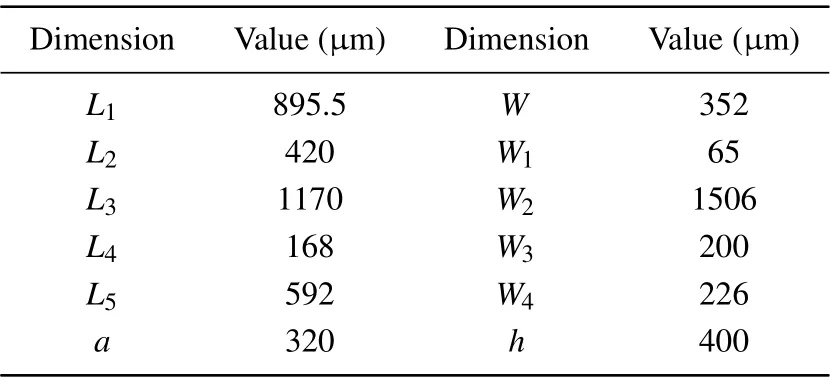
Table 1. Structural parameters of the reconfigurable comb filter.
Using the ANSOFT HFSS software,the RF performance of the four-bit filter based on MEMS switches is simulated,and the simulation results are shown in Fig. 7. Figures 7(a)-7(c)show the simulation results for theS21,S11and group delays of the filter, respectively. The filter performance of each switch state is shown in Table 2, where ‘1’ indicates that the switch is on and‘0’indicates that the switch is off.
The simulation results indicate that for a frequency range of 7-16 GHz, the maximum insertion loss of the filter is approximately 1.99 dB, the minimum out-of-band rejection is about 18.30 dB, and the maximum bandpass group delay is 0.25 ns. This four-bit filter exhibits excellent performance among reconfigurable bandpass filters,and the proposed filter can switch 16 channel frequencies with fewer switches.
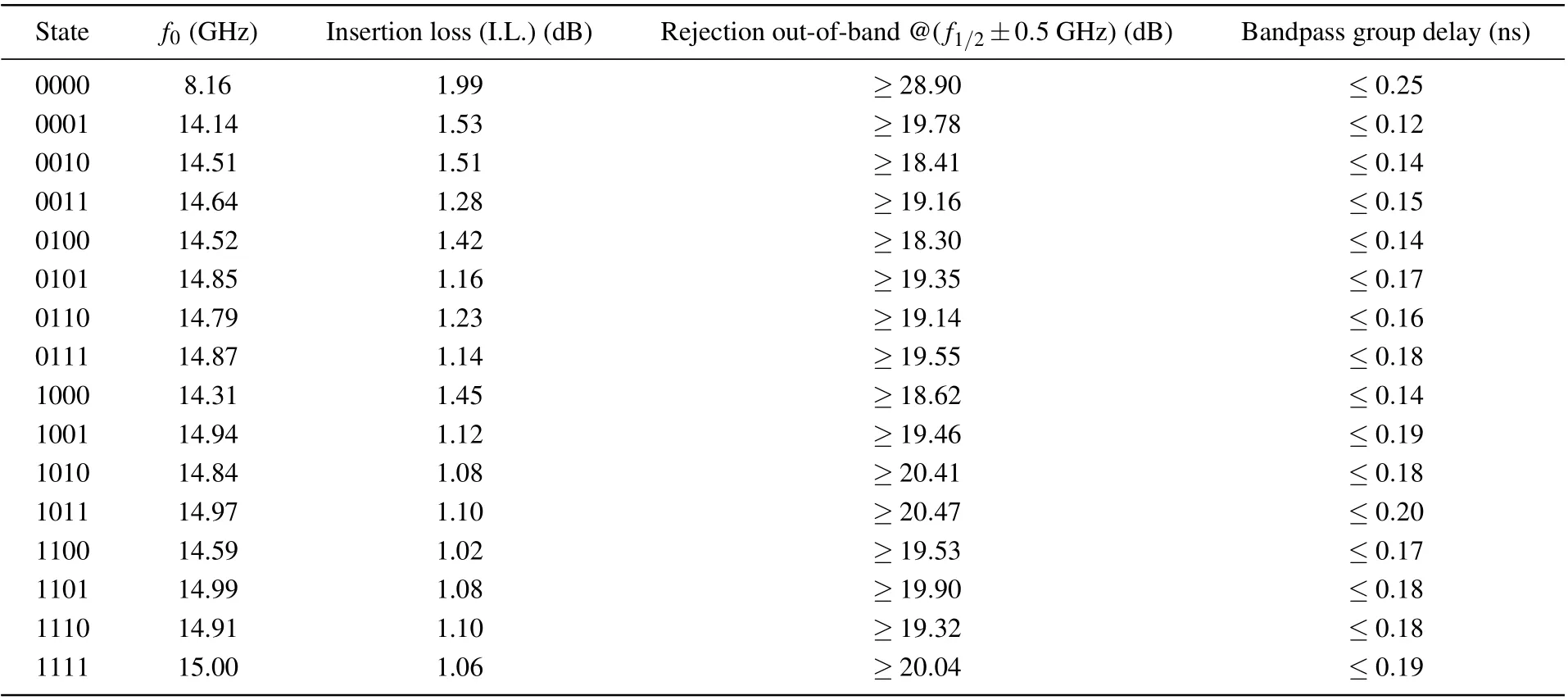
Table 2. Corresponding filter performance of each switch state. f1/2 is the frequency point of the sideband.
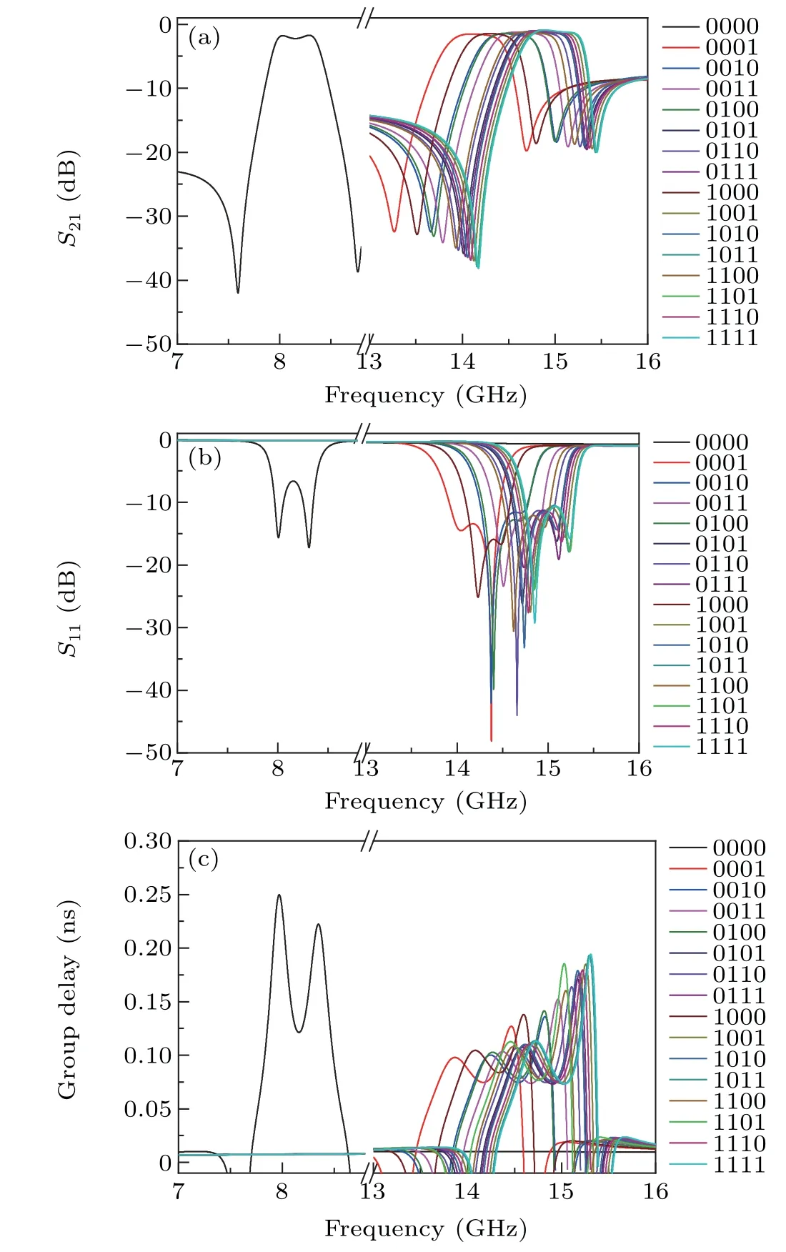
Fig.7. Simulation results for the filter: (a)S21,(b)S11,and(c)group delay.
Table 3 provides a comparison between the results for currently used reconfigurable filters and the filter designed in this study. As can be seen from Table 3,the proposed filter is able to switch 16 channel frequencies with the least number of switches,thus improving the reliability of the filter.Compared with current reconfigurable band-pass filters,the proposed filter has the advantages of low insertion loss, small size, and high integration.
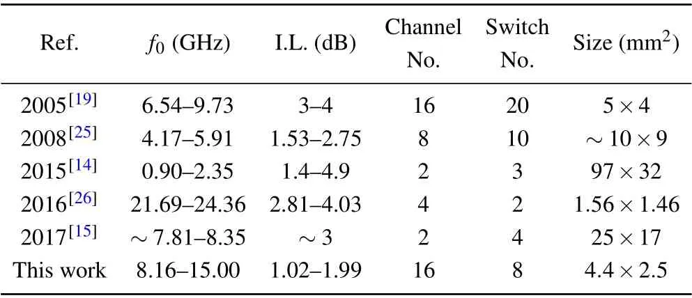
Table 3. Comparison of reconfigurable bandpass filters.
2.4. Fabrication and measurement of the RF MEMS switch
The MEMS switch, as the core device of the reconfigurable filter, is fabricated using micro-nano surface technology. Figure 8 illustrates the fabrication process of the MEMS switch.
First,a thermal oxide layer is grown by a wet etching process on a silicon wafer with a thickness of 400 μm. Second,a silicon nitride layer is deposited by plasmaenhanced chemical vapor deposition(PECVD).Third,a square silicon nitride layer is etched by reactive ion etching (RIE). Fourth, an aluminum(Al)layer is sputtered by magnetron sputtering to fabricate the drive electrode. Subsequently, an Au layer with a thickness of 2 μm is plated to fabricate the transmission line of the MEMS switch. Then,a polyimide(PI)sacrificial layer is spun and cured. Next, on the sacrificial layer, an Au layer with a thickness of 2 μm is electroplated to fabricate the top electrode. Finally,the sacrificial layer is released by RIE,and the MEMS switch is finally fabricated.9(c) show the switching on and switching off times of the switch,respectively. As the actuation signal rises from zero to the signal voltage,the switch starts to pull down and achieves a stable contact after multiple bounces; and the switching on time of the switch is about 48.2 μs. When the actuation signal drops from the pull-down voltage to zero, the switching off of the switch from the “on” state to the “off” state takes about 8.1 μs. On the other hand, reliability is a key metric of a MEMS reconfigurable filter, and the switching life of a MEMS switch can be up to 107times. After many tests, the insertion loss changed little and the repeatability was good,which confirms the performance of the reconfigurable filter.
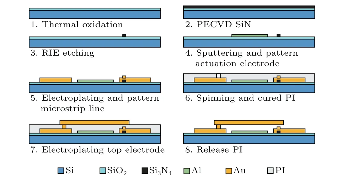
Fig.8. The fabrication processes of the MEMS switch.
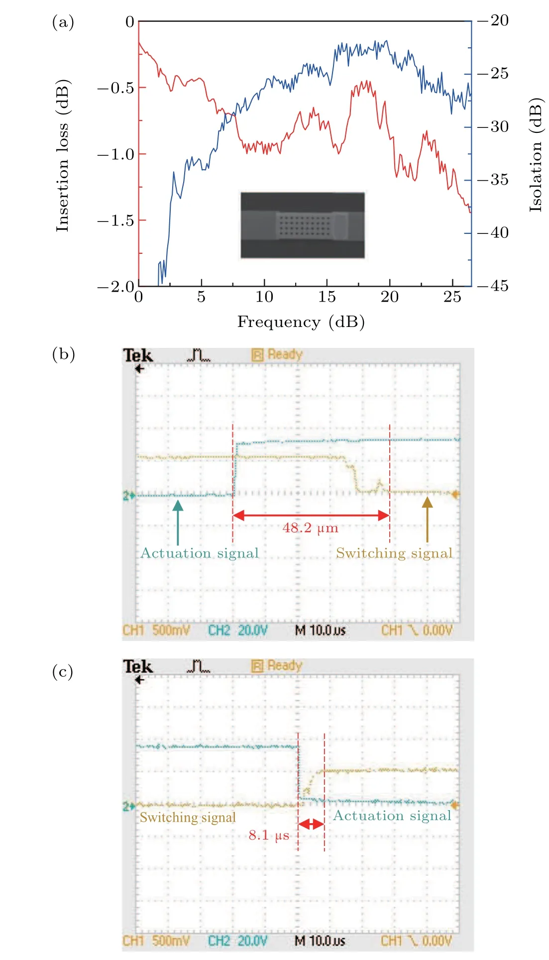
Fig.9. Measured results of the MEMS switch: (a)S21,(b)switching on time and(c)switching off time.
3. Conclusions and perspectives
In this study,the current development status of reconfigurable filters is first analyzed,and then a four-bit bandpass filter with a small size, low loss, and strong reconfigurability is designed.The terminal load capacitance of the comb resonator can be changed by MEMS switches,thus tuning the filter. The results show that this filter has good performance within a 7-16 GHz operational frequency range and can be used in multifrequency complex communication systems.As a result,it has great potential for use in channel selection,image suppression,duplexing,and multichannel communication.
Acknowledgments
Project supported by the National Defense Technology Industry Strong Foundation Project of China (Grant No. JCKY2018****06) and the Information System New items Project(Grant Nos.2018****26 and 2019****10).We thank the Key Laboratory of Instrumentation Science and Dynamic Measurement for their support.
The measured results in Fig.9(a)show that the insertion loss of the MEMS switch is approximately 1.0 dB and the isolation is more than 22.0 dB in the range of 7-16 GHz,which satisfy the design specification requirements. Figures 9(b)and
猜你喜歡
Plasma Science and Technology(2024年2期)2024-03-19 02:37:22
計算技術(shù)與自動化(2022年1期)2022-04-15 21:33:55
運(yùn)輸經(jīng)理世界(2020年1期)2020-07-23 06:48:14
食品工業(yè)(2020年6期)2020-07-18 04:07:22
人民調(diào)解(2019年6期)2019-12-23 00:05:09
水動力學(xué)研究與進(jìn)展 B輯(2017年4期)2017-09-15 13:55:51
知音·上半月(2016年9期)2016-09-20 10:44:38
故事會(2014年19期)2014-09-25 14:08:10
Defence Technology(2011年2期)2011-03-09 11:57:02
Chinese Journal of Chemical Engineering(2009年6期)2009-05-15 01:40:14

- Chinese Physics B的其它文章
- Role of compositional changes on thermal,magnetic,and mechanical properties of Fe–P–C-based amorphous alloys
- Substrate tuned reconstructed polymerization of naphthalocyanine on Ag(110)
- Anti-PT-symmetric Kerr gyroscope
- Information flow between stock markets:A Koopman decomposition approach
- Cascading failures of overload behaviors using a new coupled network model between edges
- High efficiency ETM-free perovskite cell composed of CuSCN and increasing gradient CH3NH3PbI3