
Ultrafast structural dynamics using time-resolved x-ray diffraction driven by relativistic laser pulses?
2021-09-28 02:18:44ChangQingZhu朱常青JunHaoTan譚軍豪YuHangHe何雨航JinGuangWang王進(jìn)光YiFeiLi李毅飛XinLu魯欣YingJunLi李英駿JieChen陳潔LiMingChen陳黎明andJieZhang張杰
Chinese Physics B 2021年9期
Chang-Qing Zhu(朱常青),Jun-Hao Tan(譚軍豪),Yu-Hang He(何雨航),Jin-Guang Wang(王進(jìn)光),Yi-Fei Li(李毅飛),Xin Lu(魯欣),3,Ying-Jun Li(李英駿),Jie Chen(陳潔),Li-Ming Chen(陳黎明),?,and Jie Zhang(張杰),
1Beijing National Laboratory of Condensed Matter Physics,Institute of Physics,Chinese Academy of Sciences,Beijing 100190,China
2School of Physical Sciences,University of Chinese Academy of Sciences,Beijing 100049,China
3Songshan Lake Materials Laboratory,Dongguan 523808,China
4State Key Laboratory for GeoMechanics and Deep Underground Engineering,China University of Mining and Technology,Beijing 100083,China
5Department of Physics,College of Science,China University of Mining and Technology,Beijing 100083,China
6IFSA Collaborative Innovation Center and School of Physics and Astronomy,Shanghai Jiao Tong University,Shanghai 200240,China
Keywords:ultrafast x-ray diffraction,transient structural changes,multilayer mirrors
1.Introduction
The table-top sub-picosecond hard x-ray source from laser-irradiated plasmas has been studied for many years[1–3]with the rapid development of laser technology.Due to its tremendous advantages in ultrashort pulse duration,high peak brightness,and small source size,this kind of source has been widely used in micro-radiography/phase contrast imaging,[4–6]time-resolved x-ray absorption spectroscopy,[7–9]and femtosecond x-ray diffraction[10–19]in university scale laboratories.Particularly,the ultrafast x-ray diffraction(UXRD)offers the direct perspectives of structural dynamics of atomic motions in materials on a femtosecond-to-picosecond time scale.
The efficient characteristic x-ray emission by focusing a temporally compressed laser pulse onto a solid target is associated with many parameters,including peak pulse intensity,temporal contrast,plasma scale length,etc.The conversion efficiency of Kαemission is strongly dependent on the laser peak intensity[20]and the contrast ratio between the main pulse and pre-pulse.[21,22]However,the Kαemission is somehow independent of the pulse contrast when the femtosecond laser pulse is in the relativistic intensity regime(>2×10¹⁸W/cm2).The relativistic J×B heating dominates the physical mechanism and the Kαphoton yield is not saturated with respect to the laser intensity.[23]For the time-resolved“optical-pump–x-ray-probe”diffraction experiments,the low average x-ray flux and long data acquisition time often restrict the extensive applications of the ultrafast laser-plasma x-ray system.The two-dimensional(2D)monochromatic instrument can be utilized to highly improve the x-ray intensity on the sample.[24]In terms of pulse-to-pulse fluctuations,using different normalization schemes for intensity fluctuations[25]or un-pumped area as a reference[26]can also provide a sufficient signal-to-noise ratio in experiments.Most UXRD system is operated at kHz repetition rate with low energy conversion efficiency because of its low laser intensity.[27,28]Besides,the high accumulative dose of optical pump limits the use of the system for the low damage threshold and irreversible dynamics of samples.Therefore,it is necessary to build a UXRD-facility operating with relativistic laser intensity at a low repetition rate.
In this paper,we established a setup for time-resolved xray diffraction system based on the interaction of femtosecond relativistic laser pulses with a solid target at a repetition rate of 10 Hz.We gave the detailed descriptions of the characterizations of the plasma x-ray source and optimization of multilayer mirrors.Finally,for example,we demonstrated its good performance on probing the ultrafast structural changes of a thin film SrCoO2.5sample.
2.Characterizations of UXRD system
The UXRD system was driven by a 30-fs,800-nm laser system at a repetition rate of 10 Hz at Institute of Physics,Chinese Academy of Sciences.The layout of the setup is shown in Fig.1.The p-polarized laser pulse is split into two beams by a 9:1 beam splitter.The weaker one served as the pump laser is directed onto a mechanical delay stage.Thus,the optical pump laser is temporarily shifted with respect to the x-ray probe pulse on the sample.The energy of the pump pulse is tunable by use of aλ/2 wave plate and a polarizer.A frequency doublingβ-BBO crystal is utilized to convert 800 nm to 400 nm.Only 400 nm laser beam can pass through a narrow bandpass filter.Finally,the pump laser is focused onto the sample with diameter(FWHM)~2 mm by a lens.

Fig.1.Layout of pump–probe experimental setup.
The main pulse is focused by an f=76 mm gold coated off-axis parabola(OAP)mirror with energy of~150 mJ on a copper target and laser intensity of~2×10¹⁹W/cm2.The contrast ratio of the laser pulse is better than 107at around 10 ps.Nonetheless,in the relativistic intensity regime(>2×10¹⁸W/cm2),Kαemission as well as the conversion efficiency is independent of the laser contrast ratio.The ultrafast x-rays emitted from the femtosecond high intensity laser–plasma interaction are in vacuum environment to avoid the nonlinear effects in air such as auto-focusing(Kerr effect)and self-phase modulation.[29,30]There is a thin mylar film before the solid target to block the sputtered particles.The main laser energy is focused onto the copper target at 45°from the target normal.
The 3 mm thick copper disk target is polished,with the diameter of 3 inches.The target positioning system is consisted of a rotatory stage(R1),an upper linear stage(L1),and a lower linear stage(L2),which take control of the angular,radial,and longitudinal coordinates of the target,respectively.The target surface is strictly parallel to L1 and perpendicular to the rotational axis of R1 to avoid the wobble effect.The target surface deviation is inspected by a dial test indicator(Mitutoyo 513-401E)and it is less than 4μm.The stability of the x-ray source parameter,including the pointing,flux,and energy spectra,is essential for the application of laser-driven plasma x-ray source.[31]We keep the line speed a constant to ensure a fresh target surface shot by shot.As a consequence,the angular velocity of the rotatory stage should be adjusted immediately when the laser pulse illuminates the inner radii of the target.
The generated x-ray source was collected in a solid angle by a Montel multilayer mirror[32](ELM45,from Incoatec company).This 2D compact focusing system coated on an elliptically shaped Si substrate is composed of two mirrors sideby-side in an L-shape orientation.Therefore,the Montel optics is highly suitable for the monochromatization of x-rays and 2D beam shape focusing.The monochromatic Cu Kαradiation withΔE/E~0.5% was selected and reflected to the SrCoO2.5sample.The sample at the x-ray focus(~300μm)was overfilled by the pump pulse.
The diffracted x-ray signals were collected by the front illuminated x-ray CCD(Andor iKon-M DY934P)[33]with ultralow noise readout.This detector offers high dynamic range and high spatial resolution(1024×1024 pixels of 13×13μm2size),as well as the quantum efficiency of 18% at 8.04 keV.A 200-μm thick Beryllium foil window was used to block the visible light.Additionally,the CCD was cooled down to?80°C which is critical for elimination of dark current.
In order to shield against the x-ray radiation effectively,the chamber was surrounded by several 5 mm thick lead shielding.In addition,the routing operation location where people stand is over 3 m away from the x-ray source.The average radiation level is below 0.5μSv/h which is safe for health.
The characterization of the laser focus is critical for us to measure and optimize the spot size as well as laser intensity in the vicinity of the focal plane.The beam profile was imaged by a 10×microscope objective and analyzed by a highresolution USB silicon CCD camera(OPHIR SP928).The laser focal spot was measured as~3.0μm(1/e2radius w0),as shown in Fig.2(a).The Kαx-ray spectra were resolved with the help of x-ray camera in single-photon counting regime,which consisted of pronounced Cu Kαand Kβcharacteristic lines with relatively small Bremsstrahlung continuum,as illustrated in Fig.2(b).
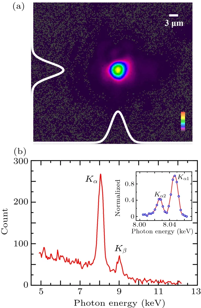
Fig.2.(a)Laser focal spot image.(b)Spectrum of laser plasma x-ray source recorded by an x-ray CCD.The illustration at the upper right panel shows the spectrally resolved fine structure components of Cu Kα1 and Kα2 x-ray emission by a 60-nm SrCoO2.5 crystal.
The generated Kαx-ray source has an intensity of 2.5×10⁸photons/sr/shot,which corresponds to an average radiation power of 20.3μW into 2πsolid angle.Assuming that the emission is isotropic,the conversion efficiency from laser energy to Kαx-ray source is calculated as 1.4×10?5.The total Kαgeneration as a function of distance with respect to the best focal spot is shown in Fig.3(a).The maximum output is observed near the best focal plane.The distribution of x-rays appears symmetric.Obviously,the emission intensity as well as the energy conversion of Kαgeneration increases with the laser intensity,which is consistent with the previous result.[23]Meanwhile,the x-ray yield increases exponentially with the laser energy.Table 1 summarizes the basic properties of the time-resolved pump–probe setup.In addition,the establishment of this facility provides us a beneficial experience for building an ultrafast x-ray dynamic experimental subsystem in Synergetic Extreme Condition User Facility.[34]

Fig.3.X-ray yield as a function of(a)distance from focus and(b)laser energy.The negative values of the distance in(a)indicate the focus locating in front of the target.While the positive values indicate the focus within the target.All solid smooth curves only serve as a guide to the eyes.The error bars represent the standard errors in measurement.The x-ray photon number measured in(b)was at a distance of?0.05 mm.
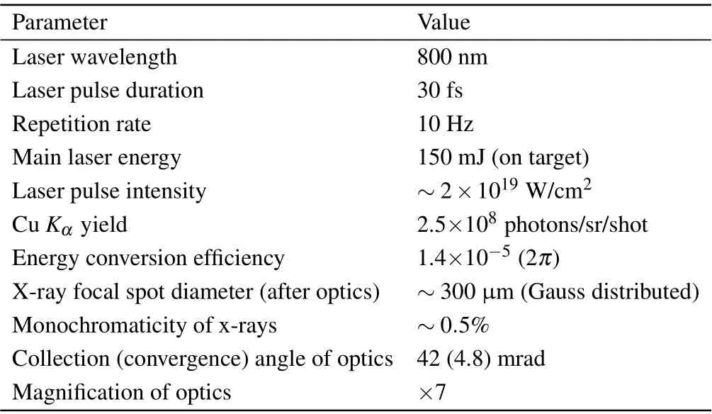
Table 1.Summary of the UXRD properties.
3.Optimization of Montel optics
Figure 4(a)is the layout of Montel multilayer optics.The optics are factory prefabricated with two perpendicular mirrors,each of which is used to shape the x-ray emission in one dimension only.The structural diagram inside the housing is shown in Fig.4(b).The spring is used to fix the mirrors onto the optics housing.The graded multilayer mirror is consisted of hundreds of pairs of layers which are deposited on the elliptically shaped Si-substrate.All movements of mirrors are actuated by the four eccentrics.When the eccentric is rotated by the alignment stage outside,the plunger will excite the mirror movement.The alignment stage provides four degrees of freedom(A1–A4)for the high precision of the optics.The two adjusting knobs A1,A3 are at the housing entry and A2,A4 at the housing exit,respectively.Each knob is motorized.
The principle scheme of Montel optics is depicted in Fig.4(c).W1 and W2,the beryllium windows,are utilized to protect the optics from being exposed to the visible light.W3 and W4 are the apertures to select the x-rays in a small solid angle to satisfy Bragg’s diffraction law.The diffracted beams will be separated from the directed beam through the optics.Finally,the beam is divided into four parts:two singly diffracted beams(B1 and B2),doubly diffracted beam(B3),and direct beam(B4).In B3,each photon is diffracted twiceonce per single multilayer mirror.
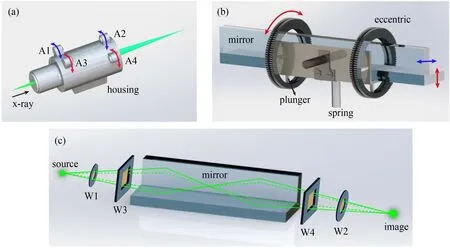
Fig.4.(a)Layout of Montel optics.A1–A4 are the adjusting knobs motorized to actuate the eccentrics.The arrows(red and blue)show the schematic for translating the exit beam.(b)Structural diagram inside the optics.(c)Principle scheme of focusing the x-ray beam.The green lines represent the trajectories of doubly diffracted x-rays.W1:beryllium(Be)window for housing entry.W2:beryllium window for housing exit.W3:aperture.W4:aperture.Actually,W3 and W4 are tightly adhered to the two mirrors.Here,we keep them separated to interpret clearly.
To align the optics,it is critical to place it at the appropriate position along the orientation of x-rays.The transverse and longitudinal coordinates,as well as the height of the optics should be adjusted by the stepper motorized stages which are below the optics housing.We use a sensitive Andor x-ray CCD to monitor the images of the beam profile.The coarse alignments of the optics are described below.Firstly,we should find the direct beam with the help of the adjusting knobs at the exit side of the housing.The other knob(exit side)might be turned simultaneously until the first singly diffracted beam appears.Then,we can observe the second singly diffracted beam as well as the doubly diffracted beam by using the other knobs at the entry side of the optics housing(see the user manual[35]).It is noteworthy that the optics should not be aligned to Kβradiation which is much weaker than Kαradiation.

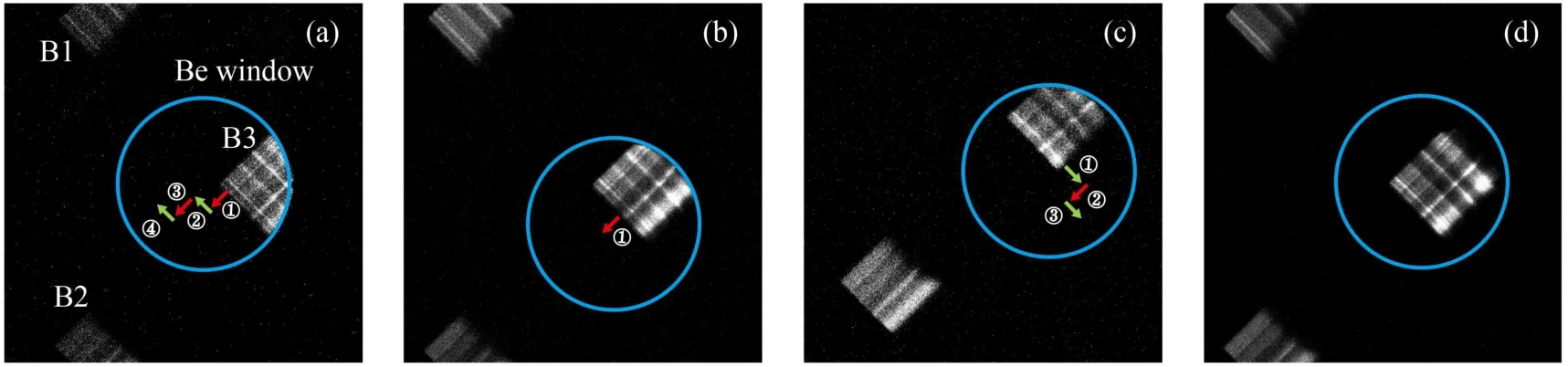
Fig.5.Images of three beams directly behind the optics housing and direct beam not visible.(a)Half of the doubly diffracted beam removed by the Be window.The arrows represent the schematic for translating the exit beam.B1 and B2:singly diffracted beams,B3:doubly diffracted beam.(b)A small portion of B3 removed by the Be window.(c)A small portion of B3 removed by the Be window in the opposite direction due to the excessive adjustment.(d)B3 passing through the Be window completely when the optics is well aligned.The diffracted beams exhibit the intensity modulations owing to the multilayer shape error.Obviously,the two singly diffracted beams reveal intensity modulations in one dimension only.While the doubly diffracted beam reveals two perpendicular modulations in intensity.The direct beam is uniform without intensity modulations.
With highly precise alignment of the optics,the typical whole beam profile is shown in Fig.6(a).The doubly diffracted beam at the focal plane has a spot size of~300μm(FWHM)and follows a single Gaussian distribution in two dimensions,as shown in Fig.6(b).

Fig.6.Images of x-ray beams at the focus position of the optics.(a)B1–B4 captured by the large area camera(Photonic Science).B4:direct beam.(b)B3 captured by the sensitive Andor x-ray camera.
4.Ultrafast dynamic x-ray diffraction
We present the typical ultrafast diffracted raw data of thin film(008)-oriented SrCoO2.5epitaxially grown on LaAlO3substrates after optical illumination,as shown in Fig.7(a).The peak position of the diffracted intensity profile is determined for the center of the x-ray spot.The images are all acquired with an exposure time of 300 s.The transient angular angle of the rocking curves relative to the original Bragg diffraction is shifted by 1.17 mrad toward smaller diffraction angle at time delay of 20 ps.Meanwhile,the broadening of the whole rocking curve is also observed.It is indicated that inhomogeneous expansion exists in the lattice system.Then,the photoinduced angular shifts after excitation for different pump–probe time delays are illustrated in Fig.7(c).
Due to the low specific heat capacity,the electrons near the sample surface are instantaneously excited and their temperature will arise after the absorption of laser energy.The electron–lattice system is in a non-equilibrium state.Then the excess energy of electrons will be transferred to the lattice through electron–phonon collisions and lead to the thermal expansion.[36]Our results demonstrate that the charge transfer dominates the non-thermal lattice deformation upon 400-nm excitation.The detailed discussion of the interplay of coupling among charge,orbital,and lattice for SrCoO2.5is complex,which is beyond the scope of this article and will be presented in the forthcoming report.[37]
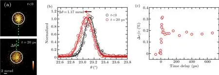
Fig.7.Ultrafast dynamic x-ray diffraction signal excited by 400-nm optical illumination.(a)Reference and signal intensity distributions from the diffraction patterns recorded by an x-ray CCD at t<0 and t=20 ps which represent before and after the arriving of the pump pulse,respectively.The incidence fluence of the pump laser is 1.91 mJ/cm2.(b)Diffraction angle scanned for(008)-SrCoO2.5 before and after pump excitation.The solid traces correspond to Gaussian curves fitted to the intensity distribution profile.(c)The photoinduced strain as a function of time delay.
5.Discussion and conclusion
In conclusion,we developed an ultrafast x-ray diffraction system employing a high pulse energy(>100 mJ)drive laser with a repetition rate of 10 Hz.We have demonstrated its ability of recording the transient processes.It is a powerful tool for the analysis of ultrafast dynamical behaviors in physics,chemistry,and biology with sub-picosecond time resolution.With this system,ultrafast photoinduced strain,laser-induced melting,and matter rearrange in atomic scale can be characterized.In addition,we will further improve the stability and the photon flux of the laser-plasma x-ray source operating at a longer period in the near further.
Our UXRD system is working at high laser intensity in the relativistic regime,which is necessary for the higherenergy Kαemission from high-Z metal materials.[38]Take Au(Z=79)target for example,an optimum laser intensity is 1.6×10¹⁸W/cm2for the highest yield of Kαx-ray emission,which ascribes to an optimal electron temperature.The relatively low accumulative dose of pump illumination at 10 Hz would be suited for the low damage threshold and irreversible dynamics of samples.[39]And,this facility exhibits high flexibilities for the different particular applications,such as phasecontrast imaging,x-ray absorption spectroscopy,and ultrafast structural detection in real time.For example,if the highpower laser beam is separated to several sub-pulses to generate individual x-ray pulses,the transient structural changes of a sample can be studied in a single-shot mode.[34]The detailed methods are depicted in Ref.[40].Besides,the singly diffracted x-ray beam might be used as an x-ray probe strip for the further diffracted experiment.
Acknowledgment
We thank Beijing TOP-UNISTAR company and INCOATEC innovative coating technologies for their technical support of optimization of Montel optics.
猜你喜歡
Chinese Physics B(2024年3期)2024-03-25 09:30:48
藝術(shù)大觀(2023年17期)2023-07-10 06:23:41
課堂內(nèi)外·小學(xué)版(低年級)(2023年2期)2023-04-29 11:48:38
山東農(nóng)機(jī)化(2016年1期)2016-03-25 05:45:25
紅蜻蜓·低年級(2015年10期)2016-01-26 11:09:21
紅蜻蜓·低年級(2014年9期)2015-03-23 02:17:58
Chinese Journal of Chemical Engineering(2014年4期)2014-07-18 11:56:13
山東農(nóng)機(jī)化(2014年3期)2014-02-25 07:11:12
紅蜻蜓·低年級(2014年2期)2014-02-19 15:14:54
山東農(nóng)機(jī)化(2013年6期)2013-10-23 06:39:02

- Chinese Physics B的其它文章
- Origin of anomalous enhancement of the absorption coefficient in a PN junction?
- Protection of isolated and active regions in AlGaN/GaN HEMTs using selective laser annealing?
- First-principles study of plasmons in doped graphene nanostructures?
- Probing thermal properties of vanadium dioxide thin films by time-domain thermoreflectance without metal film?
- An improved model of damage depth of shock-melted metal in microspall under triangular wave loading?
- Signal-to-noise ratio of Raman signal measured by multichannel detectors?