
First neutron Bragg-edge imaging experimental results at CSNS?
2021-09-28 02:18:28JieChen陳潔ZhijianTan譚志堅WeiqiangLiu劉瑋強SihaoDeng鄧司浩ShengxiangWang王聲翔LiyiWang王立毅HaibiaoZheng鄭海彪HuaileLu盧懷樂FeiranShen沈斐然JiazhengHao郝嘉政XiaojuanZhou周曉娟JianrongZhou周健榮ZhijiaSun孫志嘉LunhuaHe何倫華andTianjiaoLiang梁天驕
Chinese Physics B 2021年9期
關(guān)鍵詞:陳潔
Jie Chen(陳潔),Zhijian Tan(譚志堅),Weiqiang Liu(劉瑋強),4,Sihao Deng(鄧司浩),Shengxiang Wang(王聲翔),Liyi Wang(王立毅),Haibiao Zheng(鄭海彪),Huaile Lu(盧懷樂),Feiran Shen(沈斐然),Jiazheng Hao(郝嘉政),Xiaojuan Zhou(周曉娟),Jianrong Zhou(周健榮),Zhijia Sun(孫志嘉),Lunhua He(何倫華),and Tianjiao Liang(梁天驕)
1Institute of High Energy Physics,Chinese Academy of Sciences(CAS),Beijing 100049,China
2Spallation Neutron Source Science Center(SNSSC),Dongguan 523803,China
3Beijing National Laboratory for Condensed Matter Physics,Institute of Physics,Chinese Academy of Sciences,Beijing 100190,China
4University of Chinese Academy of Sciences,Beijing 100049,China
Keywords:neutron Bragg-edge imaging,China Spallation Neutron Source
Neutron diffraction usually provides average crystallographic and magnetic structure of crystalline materials over large volumes(usually cm3range)exposed to the neutron beam.[1–3]Bragg edges in the transmission spectrum are caused by diffracted neutrons from polycrystalline materials.dhklis the interplanar spacing(d-spacing)of the crystal lattice plane(hkl)andλis the incident neutron wavelength.According to the Bragg’s law 2dhklsin(θ)=λ,there are no diffracted neutrons beyond the wavelengthλ=2dhklsin(π/2),where 2θis the scattering angle.The so-called Bragg edge appears as a sharp edge atλ=2dhklin the transmission spectrum.The neutron Bragg-edge imaging provides the possibility to spatially exploit the coherent scattering structural information of a sample in real space with high spatial resolution down to 50μm.Two-dimensional(2D)or threedimensional(3D)distributions of crystallographic phase,texture,strain,dislocation,and crystallite size could be extracted to study materials especially for engineering,batteries,metals,and alloys.[4–11]With the development of methodologies,detectors,and neutron sources,Bragg-edge imaging experiments have been achieved at both continuous reactor source and accelerator-driven pulsed neutron source,which has been developed to be a unique tool for materials scientists.Using a two-dimensional position-sensitive detector based on the time-of-flight(TOF)method[12]at a pulsed neutron source is considered to be the most efficient way for Bragg-edge imaging.Therefore,neutron imaging instruments with Braggedge imaging mode have been expected to be built at worldleading pulsed spallation neutron sources.Now,the pulsed neutron imaging instrument RADEN at J-PARC in Japan[13]and IMAT at ISIS[14]in UK have already started the user program.Energy-resolved neutron imaging instrument(ERNI)at China Spallation Neutron Source(CSNS)[15]in China,ODIN at ESS in EU,[16]and VENUS at SNS in USA are still under construction.
In this paper,a TOF Bragg-edge imaging system built on the General Purpose Powder Diffractometer(GPPD)at CSNS is introduced.The performance of Bragg-edge imaging at CSNS is evaluated by using several steel samples.The 2D strain mappings of a bent sample are given by calculating the changes of the Bragg-edge positions.The spectral resolution of transmission spectra is studied by comparing with neutron diffraction experiment.This work could contribute to the development of neutron imaging technologies and their applications,as well as demonstrate the feasibility of the Bragg-edge imaging on ERNI at CSNS.
The physical design[17]and the first experimental results[18]of GPPD were previously described.The decoupled poisoned hydrogen moderator is selected for GPPD.The diffraction sample position in a vacuum chamber is 30 m from the moderator to achieve high spectral resolution.For Braggedge imaging experiments,a pinhole selector and a imaging sample stage are installed at 28.4 m and 33.4 m from the moderator,respectively.There are vacuum flight tubes and a diffraction sample chamber between the pinhole selector and imaging sample stage as shown in the engineering design of the Bragg-edge imaging system in Fig.1.The finally used pinhole selector with diameters D=5,10,and 20 mm yields collimation ratios of L/D=1000,500,250 for a given flight path from the pinhole to the sample of L=5 m.The sample stage has a rotation range of±135°,XY motion range of±50 mm,and Z motion range of±10 mm.Two types of neutron detectors could be installed downstream of the sample stage.A CCD based neutron detector combined with scintillation screen is used to perform conventional neutron imaging.[19]A TOF neutron detector using ceramic gas electron multiplier(GEM)with 1.56 mm pixel size is used to perform Bragg-edge imaging experiments in this research.[20]
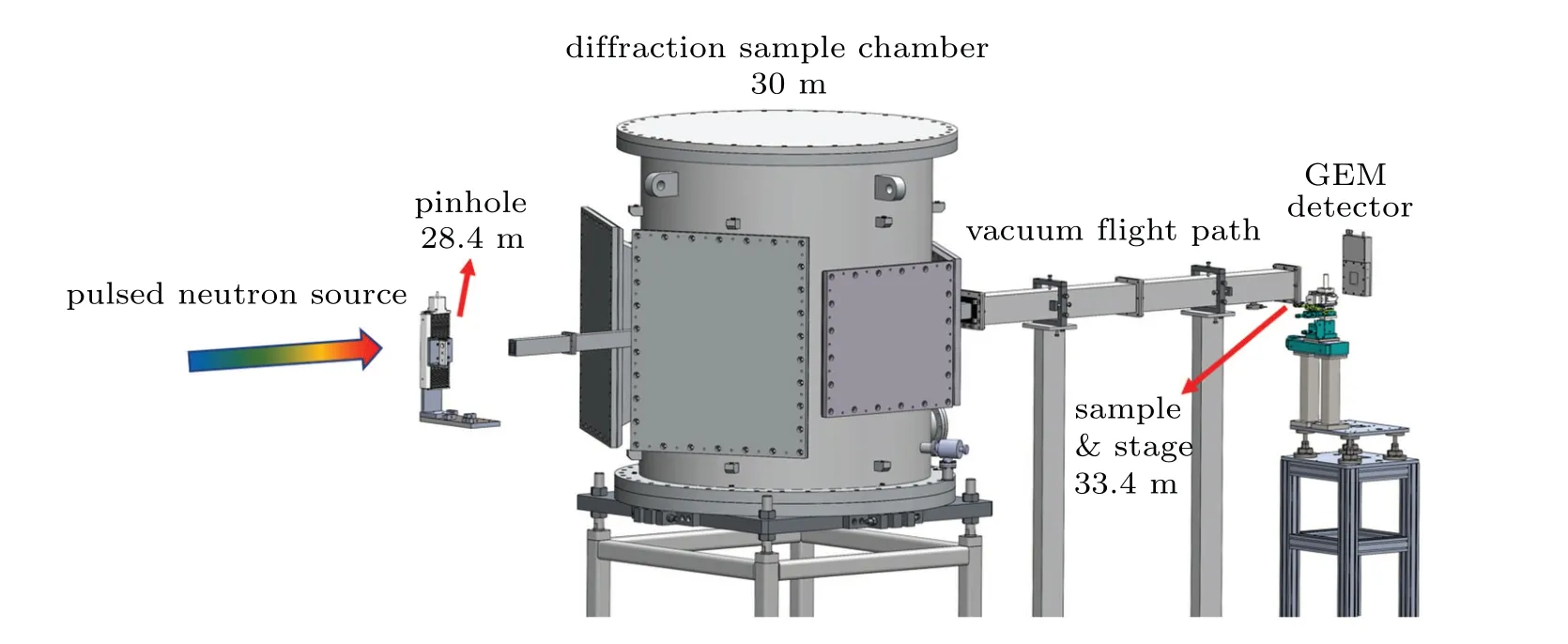
Fig.1.Engineering design of the TOF Bragg-edge imaging system on GPPD.
To experimentally demonstrate the Bragg-edge imaging on this system,we choose Q235 ferrite steel(body-centered cubic structure,bcc)and 304 stainless steel(face-centered cubic structure,fcc)plate and bent samples to perform Braggedge imaging experiments.The samples are placed at 3 cm in front of the GEM neutron detector as shown in Fig.2(a).The optical image of steel samples are shown in Fig.2(a)with a distance of 3 cm between samples and detector.The thicknesses of the plate and bent samples are 9 mm and 28.4 mm,respectively.Based on the TOF method,the Bragg-edge transmission(BET)data of each GEM detector pixel is collected in event mode.The measurement time is 14.4 hours at a proton beam power of 25 kW at CSNS.Figure 2(b)gives the conventional neutron imaging by integrating the intensity of each pixel,which shows the attenuation contrast of the samples.
The BET event data of each pixel is finally converted to BET spectra through a routine reduction procedure.The BET spectra of Q235 ferrite steel plate with a thickness of 9 mm and 304 stainless steel plate with a thickness of 12 mm are plotted in Figs.3(a)and 3(b),respectively.Theoretical BET curves have also been calculated by using pureα-Fe andγ-Fe,[21]as shown in Figs.3(c)and 3(d)for comparing indexing.According to the Beer–Lambert law,the BET pattern is calculated by the formula Tr(λ)=I/I0=e?Nσ(λ)t,where I0is the incident beam,I is the transmitted beam,N is the number of scattering centers per unit volume,σ(λ)is the total neutron cross section,and t is the thickness of the sample.Obviously,the measured transmission spectra can be indexed well by the bcc and fcc structures,respectively.
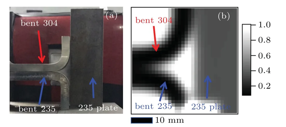
Fig.2.(a)Optical image and(b)conventional neutron image of the steel samples.
In order to confirm the quality of the BET spectra,the diffraction experiment of Q235 ferrite steel has also been performed at GPPD.Diffraction pattern is obtained by the backscattering bank with scattering angle 2θfrom 130°to 171°.Each Bragg edge of the BET spectra is matched well with the Bragg peak of the diffraction pattern,as exhibited in Figs.4(a)and 4(c).The spectral resolution of the Bragg-edge imaging mode is evaluated by fitting the differential of(110)edge using the pseudo-Voigt function which could achieve 0.15% as shown in Fig.4(b).The spectral resolution of the diffraction mode is calculated to be 0.17%by fitting the(110)peak in Fig.4(d).The spectral resolution of Bragg-edge imaging mode and diffraction mode is consistent with each other.
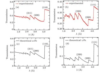
Fig.3.(a)and(b)Experimental BET spectra of the Q235 and 304 steels.(c)and(d)Theoretical BET spectra of the α-Fe and γ-Fe.
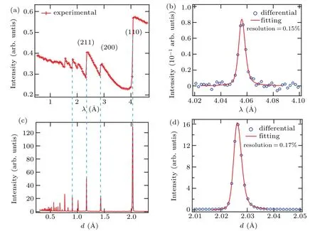
Fig.4.(a)and(c)Experimental BET spectra and diffraction pattern of the Q235 ferrite steel,respectively.(b)and(d)The spectral resolution of Bragg-edge imaging mode and diffraction mode,respectively.
The elastic strainεin crystal lattice can be calculated based on the following equation:
where d0,hklis d-spacing without strain/stress.In Bragg-edge transmission imaging,the edges appear atλ=2dhkl,deducing from Bragg’s law.A region of interest(ROI)in Fig.5(a)of the bent Q235 ferrite steel sample is chosen to calculate the 2D spatial distribution of the residual strain.The BET spectra in ROI have been re-binned twofold(2×2 pixels)to ensure enough statistics.The strain mapping along the projection has been achieved by fitting the edges[6]and calculating their relative shifts pixel by pixel.Four points have been selected to illustrate the f itting results in Fig.5(b).According to the previous works,[22–24]the distribution of strain/stress during loading in the bending experiment is tension at the outer zone and compression at the inner zone of the samples.While,after loading is removed,the macroscopic residual strain/stress distributes in a trend of tension–compression–tension–compression from the inner to the outer of the bent sample.The strain/stress distribution is caused by the elastic recovery and the non-uniform plastic deformation.[23]A strain–position curve in Fig.5(d)has been plot based on our residual strain map(Fig.5(c)),which is consistent with the trend reported in the previously mentioned works.Because of the relatively larger pixel size in the present work,we will improve the resolution and accuracy of the Bragg-edge imaging in the future work.
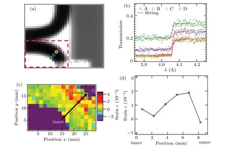
Fig.5.(a)The ROI of the bent Q235 ferrite steel sample.(b)The fitting results of the selected four points.(c)The residual strain mapping of the ROI.(d)Strain–position curve along the black solid arrow in(c).
In summary,the 2D TOF neutron Bragg-edge imaging has been achieved for the first time in China.The results demonstrate the potential and efficiency of this quantitative technique to visualize the spatial distributions of crystallographic information.As a dedicated neutron imaging instrument at CSNS,ERNI chooses a coupled hydrogen moderator as its neutron source.It has higher flux in the cold neutron range which could covering most Bragg edges of metals.A 35-m flight path could provide a reasonable spectral resolution better than 0.5%.Research and development activities of Bragg-edge imaging are still continued for the ERNI project to serve domestic users of multidisciplinary fields.It can be a key analysis tool of this neutron imaging instrument for materials science and engineering.
猜你喜歡
藝術(shù)大觀(2024年11期)2024-06-26 15:51:10
Chinese Physics B(2024年3期)2024-03-25 09:30:48
藝術(shù)大觀(2023年17期)2023-07-10 06:23:41
Plasma Science and Technology(2022年5期)2022-06-01 07:55:32
數(shù)學(xué)學(xué)習(xí)與研究(2022年2期)2022-05-10 00:05:46
河北畫報(2021年4期)2021-06-16 06:18:16
知音·上半月(2017年7期)2017-07-17 17:36:31
藝術(shù)評論(2017年5期)2017-06-14 11:38:38
愛你(2016年11期)2016-04-11 02:13:46
晚報文萃(2015年10期)2015-12-15 08:58:56

- Chinese Physics B的其它文章
- Origin of anomalous enhancement of the absorption coefficient in a PN junction?
- Protection of isolated and active regions in AlGaN/GaN HEMTs using selective laser annealing?
- First-principles study of plasmons in doped graphene nanostructures?
- Probing thermal properties of vanadium dioxide thin films by time-domain thermoreflectance without metal film?
- An improved model of damage depth of shock-melted metal in microspall under triangular wave loading?
- Signal-to-noise ratio of Raman signal measured by multichannel detectors?