A high efficient device to accelerate rotor in an alternating magnetic field
2021-03-15 03:08:16CHENLeiHEXiaoxiaLIDongmeiLIHaixiaZHANGRong
中國慣性技術(shù)學報 2021年6期
CHEN Lei, HE Xiaoxia, LI Dongmei, LI Haixia, ZHANG Rong
(Department of Precision Instrument, Tsinghua University, Beijing 100084, China)
Abstract: Accelerating or retarding a conducting rotor in alternating or uniform magnetic field is widely used in many applications such as torqueing and stabilizing electrostatic gyros, attitude control reaction sphere, and field supported ultra-high-speed centrifuges. Generally, the magnetic device with large air gap is hard to gain high efficiency. By optimize the winding shape, a high efficient device to accelerate a conducting rotor in an alternating magnetic field is proposed. Firstly, the key factors of improving the device’ efficiency are elucidated. Then the magnetic equivalent circuit based on the device’s structure is modeled. The magnetic flux across the sphere is solved in terms of the Kirchhoff’s law. Factors including core material and size, air gap, leakage flux, winding loss and magnetic field uniformity are examined and some general guidelines to improve the efficiency are deduced. Based on those guidelines, a wider winding shape that generate a more uniform magnetic field with the constraint of the device size is suggested.Furthermore, a 3-D Finite Element Model (FEM) is developed and those are verified by simulation. Two prototypes with narrow winding and wide winding are compared via accelerating experiment. Test results show that the wide winding gains about 2 times as much of accelerating torque and half Joule heat loss than narrow one.
Key words: accelerating a rotor; alternating magnetic field; finite element analysis; equivalent magnetic circuit
Accelerating or retarding a conducting rotor in alternating or uniform magnetic field is widely used in many applications, such as stabilizing electrostatic gyros[1,2], attitude control reaction sphere[3-5], field supported ultra-high-speed centrifuges[6]and other similar scenario. The performance of the device is highly dependent on its efficiency and improving the device’s efficiency is in pressing need.
The theory of the device for accelerating or retarding a sphere is similar with that of Induction motor.The alternating field with a proper frequency induces eddy currents to react with the applied field to produce acceleration torques and the stationary field produces retarding torque for a spinning sphere[7,8]. Based on this theory, the accelerating device is designed with specific winding configuration. To increase the torque, it’s demanding to improve the device’s efficiency by figuring out the key factors for the accelerating torque.
To gain high rotational speed, the sphere is sealed in a vacuum housing and the accelerating device outside of housing, which means the device has a large air gap and is hard to gain high efficiency. Meanwhile, it is possible to improve the efficiency by optimizing the magnetic path and winding shape. There are mainly four basic tools to evaluate the performance of magnetic devices including analytical models, winding function theory,Magnetic Equivalent Circuit (MEC), and Finite Element Analysis (FEA). Analytical models and winding function theory are much faster than FEA but less accurate and less flexible. MEC models represent a compromise between the accuracy and flexibility of FEA models and the speed of analytical models[9]. In this paper, we integrate the three methods of analytical models, MEC and FEA to systematically optimize the accelerating device.
We start with the geometry of the two-phase twopole accelerating system. In section 2, the magnetic equivalent circuit is modeled. Magnetic flux is expressed by magnetic reluctance. According to the acceleration torque equation, we identified several factors including core material and size, air gap, winding loss and magnetic field uniformity. Therefore, their effects on the efficiency of the accelerating system are examined and some general guidelines are summarized. Section 3 presents the 3-D FEM simulation and experimental results are demonstrated in Section 4. We conclude the paper in Section 5.
1 Geometry and equations
1.1 Geometry
We illustrate the geometry with two-phase two-pole scheme for accelerating a sphere in alternating magnetic field as shown in Fig.1. The rotating spherical conducting shell is placed in the center. An alternating magnetic field is produced by two pairs of windings coiled on four pole tips of a toroidal core.
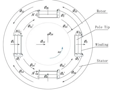
Fig.1 Two-phase two-pole accelerating device with alternating magnetic field
To define the system clearly, we introduce the symbols as follows.
Ni1,Ni2,Ni3,Ni4—Magneto-motive force of the four windings with polarity determined by right hand rule.
φ1,φ2,φ3,φ4—Magnetic flux within the four pole tips.
Obviously,φ13andφ24are effective magnetic flux through the sphere.
1.2 Accelerating torque
According to Arthur F. Hayes[8]and additional calculating, we obtain the following equation for the theoretical accelerating torqueTzalong the sphere rotating axiszin an alternating magnetic field
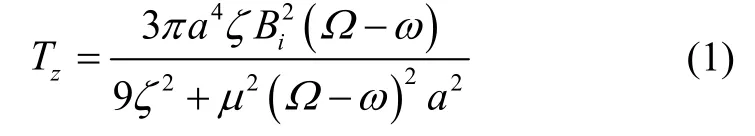
Where,Ω—alternating magnetic field angular frequency.ω—rotating angular frequency of the sphere.α—radius of the sphere.ζ—surface resistivity of the sphere.μ—permeability of the sphere.
Because magnetic fluxφis proportional to flux densityB, it can be deduced from Eq.1 that the accelerating torque is proportional to square ofφ13andφ24. So maximizing the efficiency of the accelerating torque is converted to maximizeφ13andφ24.
1.3 Magnetic equivalent circuit
According to Fig.1, the magnetic equivalent circuit is modeled as Fig.2.
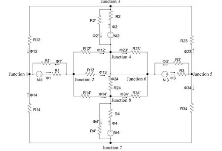
Fig.2 Magnetic equivalent circuit of the accelerating device
Where,R1,R2,R3,R4—Reluctance of the four pole tips.
R12,R23,R34,R14—Reluctance of the toroidal core between any two of adjacent pole tips.
R13,R24—Reluctance of the air between two i nphase pole tips.
Ignoring both hysteresis and saturation, we can get the reluctance as follows.

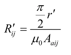
Where, ?i—Length of thei-th pole tip.r—mean radius of the toroidal core.r′—mean radius of the toroidal air outside the core.μC—permeability of the core.μ0—permeability of free space.Ai—Cross section area of thei-th pole tip.Ali—Leakage magnetic area between pole tip and winding.Atij—Cross section area of the toroidal ring between thei-th andj-th pole tips.Aaij—Cross section area of the air between thei-th andj-th pole tips.
With a known structure of accelerating device, all the reluctances can be calculated or estimated, so the unknown magnetic flux can be solved according to Kirchhoff’s voltage and current law.
In total there are 18 unknown magnetic flux including,φ1,φ2,φ3φ4,,,,φ12,φ23,φ34,φ14,φ13,φ24,,,and. Among whichφ13andφ24are the magnetic flux we want to solve next.
1.4 Magnetic flux equation
At Junction 1-8 shown in Fig.1, the total magnetic flux entering a junction is equal to the total magnetic flux leaving the same junction, we can get equation of (2)-(9)as follows.

Checking the close loop between any two of the four sources, we have equation of (10)-(15).
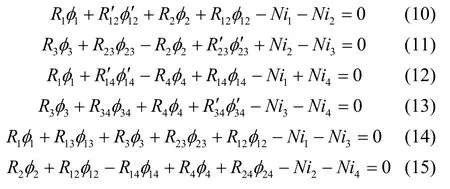
Selecting the outermost and innermost loops,equation of (16)-(19) can be deduced.

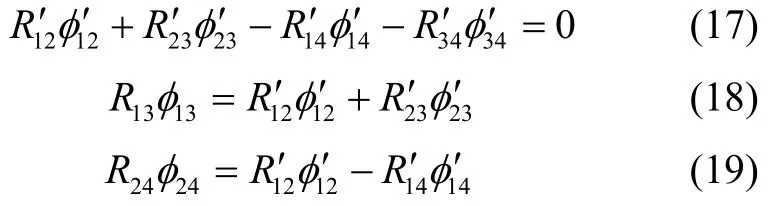
The single magneto-motive force source loop can be used to build equation of (20)-(23).

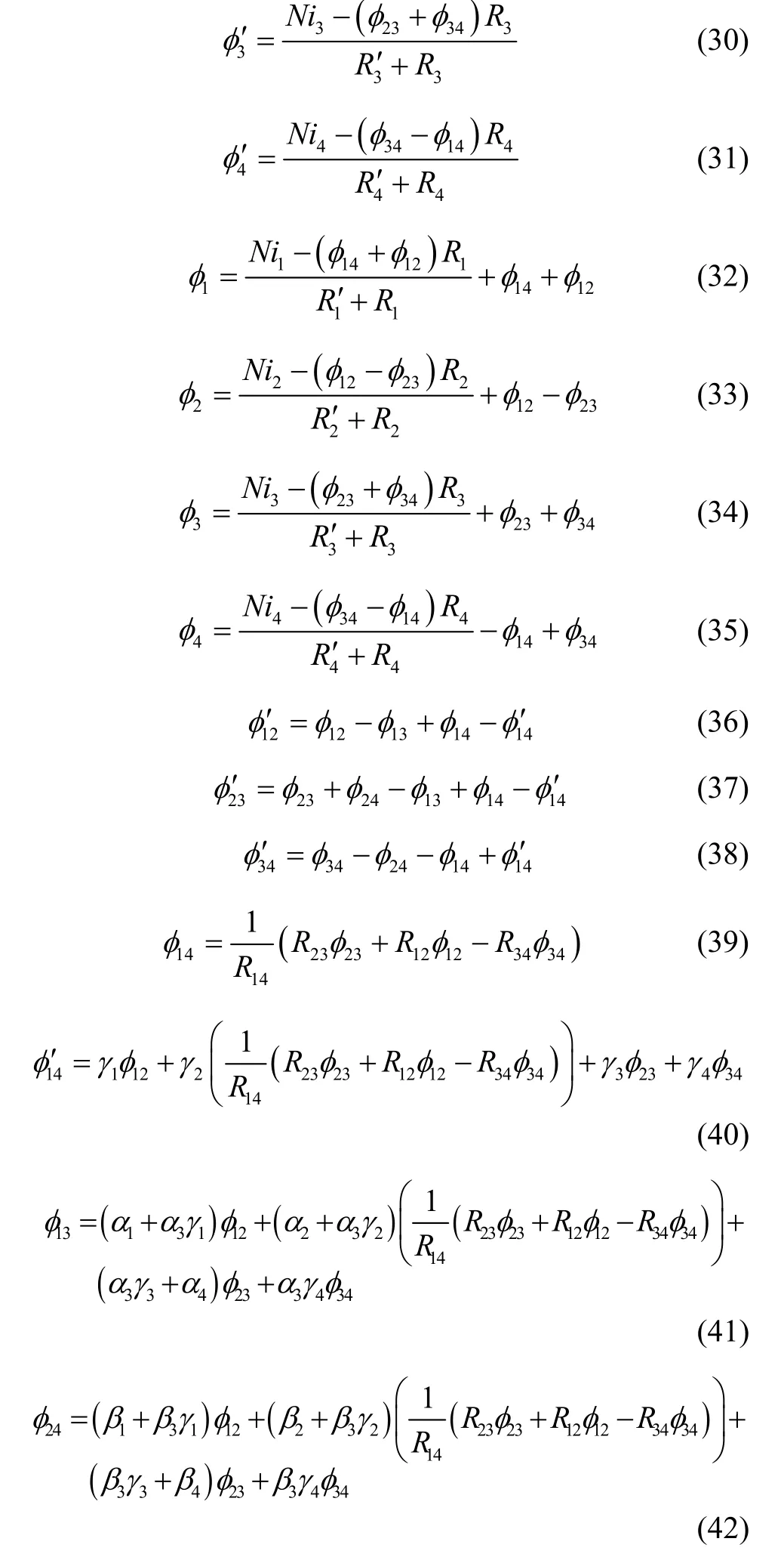
The equations above are algebra equations and its analytic solutions are given in appendix.
According to the appendix, the following engineering proper simplicity can be set without arising large error.

Furthermore,andR24are much larger thanR1andR12in the case where the permeability of the core is much greater than the permeability of air. Hence,we can get

1.5 Windings
From Eq.(24) and Eq.(25), we need to know the winding current. It is determined by windings and the whole construction of the magnetic circuit. The equivalent impedance of the windings can be expressed as follows.

WhereR0,L,ρ, ?, andRware resistance,inductance, resistivity, mean length per turn and reluctance of the winding respectively. Then, the alternating current of the winding is:

Where V1,2is the voltage applied to the winding.Substitute the above equation into Eq.(24) and Eq.(25),

Now, the flux through the sphere is expressed by reluctance and winding parameters, we can analyze their effect on accelerating torque.
1.6 Guidelines
From Eq.(1) and Eq.(25), we deduce the following guidelines to maximizeφ13andφ24to get higher torque.
Guideline #1:The core should be chosen to makeR1as small as possible to maximize. According to, larger section area and material with higher permeability should be chosen.
Guideline #2:The air gap between two in-phase pole tips should be as small as possible to reduce reluctanceR24. This means the pole tips should be designed as close to the sphere surface as possible.
Guideline #3:Eq.(24) and Eq.(25) calculates the magnetic flux passing through the rotor through a simplified magnetic circuit model when the magnetic flux is perpendicular to the respected axis. During operation, the coil will generate a rotating magnetic field.When the direction of the magnetic field rotates to a certain direction between the x and y axis, the magnetic circuit model suggests that there is no pole tips and windings in this direction. Thus, the magneto-motive force is weaker and the reluctance is stronger, which results in lower magnetic flux in this direction. Eq. (1) is deduced based on the magnetic field is uniform along x and y direction which means the magnetic field around the sphere surface should be as uniform as possible to makeφ13andφ24fluctuating less. A wide-winding design can increase the magneto-motive force to reduce magnetic field fluctuation.
The above guidelines are not all compliant with each other. Within the structure size, the winding size and pole tip section area should be compromised.Furthermore, uniformity of the magnetic field should be considered carefully by optimizing the winding and pole tip structure.
2 Simulation and experimental result
To verify the guidelines deduced from EMC equations. Several simulations are carried out using finite element analysis (FEA) Method. Constrained by the sphere size and permitted space, we designed two types of windings to examine the effect of magnetic uniformity on accelerating efficiency. Secondly the situations of toroidal core and pole tip made from high and low permeability are checked respectively. Finally, the pole tip size and air gap between in-phase pole tips are simulated.
The acceleration device includes a stator which is a toroidal core with 4 pole tips, and 4 winding coils around each pole as shown in Fig.3. Geometric parameter is given in Tab.1. The following simulations are all based on the same parameter if no additional notification is given.

Tab.1 simulation parameters
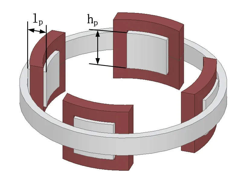
Fig.3 Illustration of four narrow windings around pole tips
2.1 Pole tip section area
Guideline #1 suggests that larger pole tip section areaAiresults in higher torque. Pole tip section area can be enlarged by increase Pole tip heighthp. Pole tip height ranging from 8 mm to 28 mm are simulated and the result is shown in Fig.4.
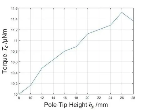
Fig.4 Torque with respect to pole tip height
Simulation results suggests the torque increases with higher pole tip height. This approves our guideline#1.
2.2 Material permeability of stator
Guideline #1 also suggests stator material permeability affects acceleration torque. Stator core’s relativity permeability ranging from 1 to 50000 is simulated to help select core material from air to the general magnetically permeable material. Result is given in Fig.5.
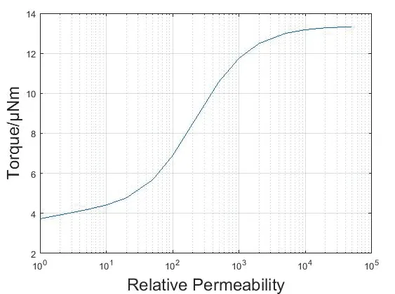
Fig.5 Torque with respect to stator relative permeability
Simulation results suggests that higher stator permeability helps to increases torque, which is approval to guideline #1. However, when relative permeability is above 20000, the torque increases very slowly. We choose 1J85 permalloy to make the stator, which has a relative permeability about 40000.
2.3 Air gap between in-phase pole tips
Guideline #2 requires the air gap between two inphase pole tips to be as small as possible. In-phase pole tip distance can be reduced by prolong the length of the pole tipslp. A simulation with pole tip length from 0 mm to 10 mm is carried out as shown in Fig.6.

Fig.6 Effect of air gap on torque
From the simulation result we can see that the smaller air gap, i.e. longer pole tip length, the higher torque is obtained. This approves our guideline #2.
2.4 Magnetic field uniformity
To increase the uniformity of magnetic field,guideline #3 suggested a “wide-winding design”.Windings tightly centered around the pole tips are called narrow winding as Fig.3 shows. To improve the uniformity of the magnetic field, a novel design featuring wide windings distributed along the inner radius of the stator core is proposed, and it is called “wide winding”.To maximize the width of windings, the windings overlaps each other. The wide winding design is illustrated in Fig.7. The stator core parameters remain the same with narrow winding design in Tab.1, and the winding number of turns reduced half to maintain the same volume with narrow windings.

Fig.7 Wide winding design
Simulations are carried out to evaluate the performance of new design. Fig.8 and Fig.9 shows the magnetic field distribution of the two designs. It shows that the magnetic field generated by narrow winding is concentrated around pole tips. While the field of wide winding is more uniform.Usingto measure the non uniformity of the magnetic field at point, we can calculate the non uniformity of the magnetic field within the area of the rotor. The result is given in Tab.2, and it suggests the magnetic field of wide winding is about 3.5 times more uniform than narrow winding.
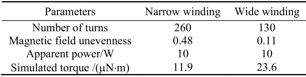
Tab.2 Simulated torques of two type of windings
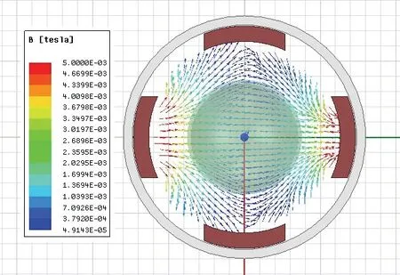
Fig.8 Magnetic field of the narrow winding
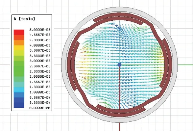
Fig.9 Magnetic field of the wide winding
Accelerating efficiency of these two types of windings is also simulated and the result is shown in Tab.2. The simulation results show that the wide winding not only has more uniform magnetic field, but also doubled the torque than narrow winding. The simulation result is compliant with the guideline #3.
3 Experimental result
To examine the performance of wide winding design compared to narrow winding, both windings are built. The rotor is a sphere metal shell that is electro statically suspended in the center of the winding in a vacuum chamber. The whole experiment setup is shown in Fig.10, and the parameters is given in Tab.1.

Fig.10 Experiment devices
The two different designs have different electrical circuit parameters. Therefore, same driving voltage applied to both narrow and wide windings will have different power consumption. To acquire a comparable result, different driving voltage is applied to achieve same apparent power consumption. Driving voltage,phase current and other respective electrical parameters are given in Tab.3.

Tab.3 Experimented torques of two windings.
During rotor acceleration experiment, the spin speed of the rotor is recorded and shown in Fig.11. The spin speed is then mathematically converted into acceleration speed and further translated into torque. The result is given in Fig.11 and Fig.12.

Fig.11 Sphere spin speed versus time
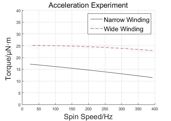
Fig.12 Torque with respect to spin speed
The result shows that the torque decreased as rotor spin speed increased, this is due to change in slip rate.
Experiment result shows the wide winding design gains 0.96 times more accelerating torque than narrow winding, which coincide with the simulated result.
4 Conclusions
In this paper, we deduced three general guidelines for the device of accelerating sphere in alternating field based on the magnetic equivalent circuit and finite element simulation. A wide winding design is put forward to generate more uniform magnetic field.Experimental prototypes are built, and prove the wide winding design gains 0.96 times more accelerating torque than narrow winding one.
Appendix
According to Eq.(10) to Eq.(25), we can get

Where

So, only three flux ofφ12,φ23andφ34are unknown.
Letx=[φ12φ23φ34]T, according to Eq.(10) to Eq.(23), We get

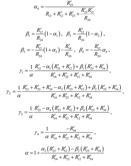
Where
From Eq.28 and Eq.29, all the magnetic flux can be solved. With engineering proper simplicity, we have


Substitute the above equations into Eq.(28)-Eq.(42),the other flux can be solved.