
Numerical investigation on adiabatic film cooling effectiveness and heat transfer coefficient for effusion cooling over a transverse corrugated surface
2017-11-20 12:07:19QuLihongZhngJingzhouTnXiomingWngMinmin
CHINESE JOURNAL OF AERONAUTICS 2017年2期
Qu Lihong,Zhng Jingzhou,b,*,Tn Xioming,Wng Minmin
aCollege of Energy and Power Engineering,Jiangsu Province Key Laboratory of Aerospace Power System,Nanjing University of Aeronautics and Astronautics,Nanjing 210016,China
bCollaborative Innovation Center of Advanced Aero-Engine,Beijing 100083,China
Numerical investigation on adiabatic film cooling effectiveness and heat transfer coefficient for effusion cooling over a transverse corrugated surface
Qu Lihonga,Zhang Jingzhoua,b,*,Tan Xiaominga,Wang Minmina
aCollege of Energy and Power Engineering,Jiangsu Province Key Laboratory of Aerospace Power System,Nanjing University of Aeronautics and Astronautics,Nanjing 210016,China
bCollaborative Innovation Center of Advanced Aero-Engine,Beijing 100083,China
Adiabatic film cooling effectiveness;Effusion cooling;Heat transfer;Numerical computation;Transverse corrugated surface
Three-dimensional numerical computations are conducted to investigate the effects of the blowing ratio and corrugation geometry on the adiabatic film cooling effectiveness as well as the heat transfer coefficient over a transverse corrugated surface.It is noticeable that the adiabatic wall temperature on the wavy valley of the transverse corrugated surface is relatively lower than that on the wavy peak.Surface corrugation has a relatively obvious influence on the laterallyaveraged adiabatic film cooling effectiveness in the region where the effusion film layer is developed,but has little influence in the front region.Compared to a flat surface,the transverse corrugated surface produces a smaller adiabatic film cooling effectiveness and a higher heat transfer coefficient ratio.The effusion cooling difference between the flat and corrugated surfaces behaves more obviously under a small aspect ratio of the wavy corrugation.
1.Introduction
Effusion cooling is regarded as a more ideal cooling scheme for protecting the combustor liners of aero-engines.1–3Earlier research presented by Andrews et al.4–6revealed preliminarily the effects of main geometric and aero-thermal factors on the thermal and aerodynamic performances of an effusion cooling scheme.Bohn and Moritz7,Scrittore et al.8,and Yang and Zhang9,10investigated numerically or experimentally the developing process of coolant jets injected from effusion holes.It waspointed outthatanasymptotic ‘fullydeveloped”adiabatic effectiveness level or velocity profile is established at a certain streamwise location.From this location on,the averaged adiabatic film cooling effectiveness should tend to be constant.Lin et al.11and Zhang et al.12conducted experiments to reveal the effects of the hole-array arrangement and holedeflection angle on the effusion cooling effectiveness.More recently,Ligrani et al.13,14performed an experimental investigation on full-coverage film cooling for dense and sparse hole arrays at different blowing ratios.Comparisons of adiabatic effectiveness,heat transfer coefficients,and net heat flux reduction(NHFR)for sparse and dense hole arrays were presented.Andreini et al.15made an experimental and theoretical investigation on the overall cooling effectiveness of multi-perforated plates.It was reported that a geometry with tilted holes shows the best wall protection under low blowing ratios.On the contrary,for high blowing ratios,a normal hole array provides a slightly better overall effectiveness.
Most of the previous studies focused on effusion cooling over aflatsurface.However,veryfewworkswerereportedoneffusion cooling over a corrugated surface which is encountered in an aero-engine with an afterburner.The afterburner’s heat shield usuallyhasaperiodiccorrugatedfoldforthepurposeofstrengthening its structure,and the length-to-diameter ratio of the film hole used for the heat shield is usually relatively small in actual engineering.The injection angle of the film hole is normal to the corrugated surface.Thus,the coherence between the film injection and the mainstream is different compared with a flat plate.Shinboetal.16presentedanexperimentalstudyontheconvective heat transfer over a longitudinal corrugated surface.It was concluded that the convective heat transfer in the case of a corrugated plate is larger than that obtained from a flat surface,mainly due to the influence of the plate corrugation on the development of turbulence near the wall region.Champion et al.17studied experimentally the flow structure over a longitudinal wavy surface involving multi-holes regions.They showed that anincreaseoftheblowingratefrom0.8to2.5leadstoanincrease andamoreuniformstreamwisedistributionoftheadiabaticwall effectiveness.Funazaki et al.18performed an experiment on the aerodynamic behaviors of the air ejected from several discrete hole rows and the resultant film effectiveness over a longitudinal corrugated wall.It was indicated that the jet cores tend to diminish much faster than those in a flat-plate case,probably due to a mixing ofthe high-momentum jetand low-momentum air onthe valley of the corrugated wall.A group led by Chang dedicated a series of combined numerical and experimental publications on discrete-holes film cooling and effusion cooling over a longitudinalcorrugatedwall.19–22Toourknowledge,nearlynoattentionis paid to effusion cooling on a transverse corrugated surface.
The motivation of the presented numerical study is to explore the effusion cooling characteristics over a transverse corrugated surface.Effects of the blowing ratio and the amplitude and wavelength of the corrugated wall on the adiabatic film cooling effectiveness as well as the heat transfer coef ficient are concentrated on.
2.Computation scheme
2.1.Brief description of physical model
Considering the periodic structure of a transverse corrugated surface,one wavelength alongy-direction is taken as the computational domain,as seen in Fig.1(a).The height and length of the primary flow passage are chosen as 80 mm and 518 mm,respectively.The perforated port has a length of 198 mm and is located in the middle section of the computational domain.The coordinate origin is located at the center line of the corrugation as well as the starting edge of the perforated port.
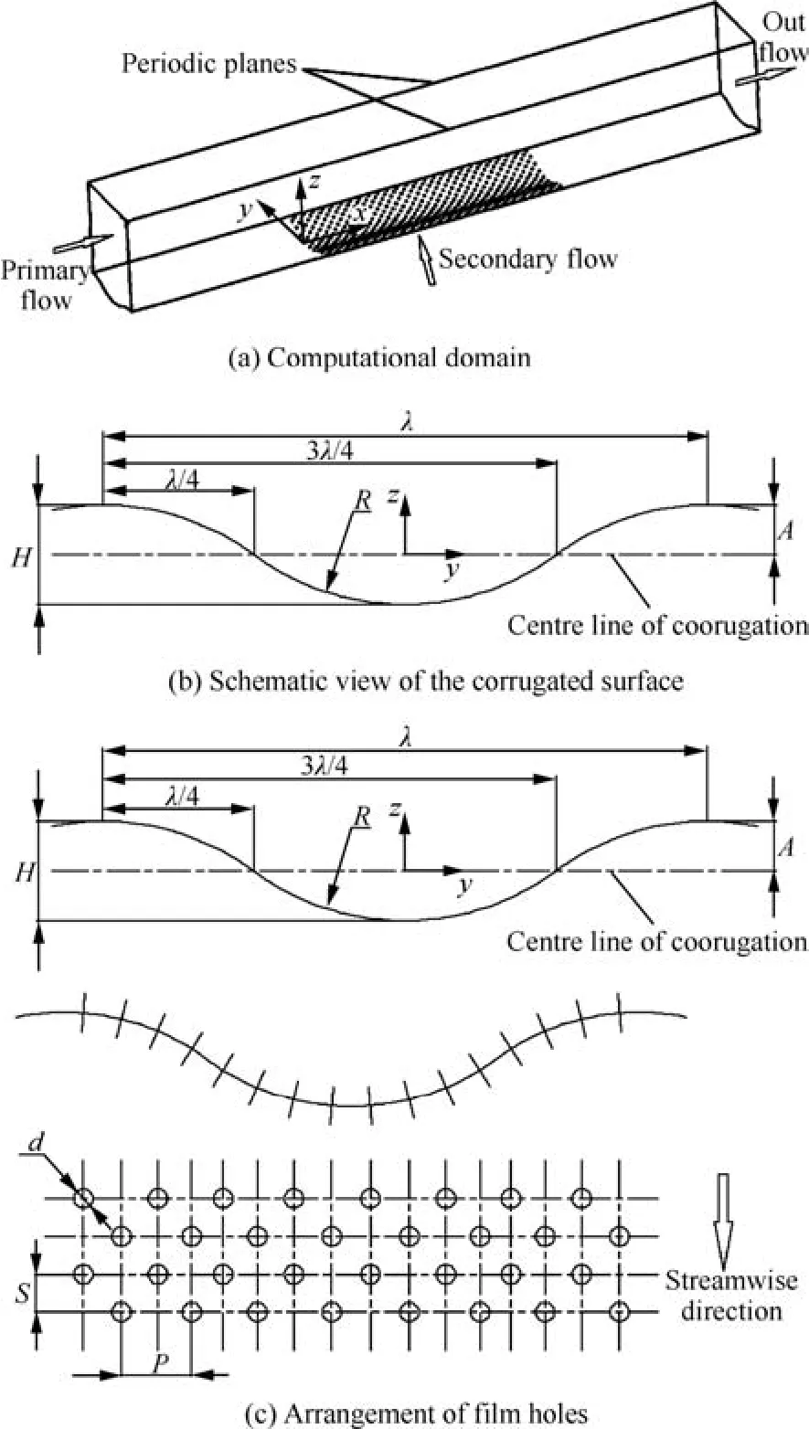
Fig.1 Schematic computational model.
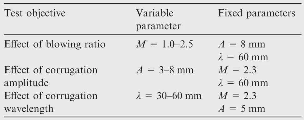
Table 1 Parameters tested in the present.
2.2.Computational approach and validation
Three-dimensional numerical simulation is employed by using Fluent-CFD software.According to that the realizablek-e turbulence model has been proved to provide reasonable computational results of film cooling23–25,thus the realizablek-e turbulence model is used in the current study to model turbulence,and the near wall region is modeled using enhanced wall functions.
The computational meshes are divided in the same treatment as that by Yang and Zhang.9Four grid-blocks are involved in the present computation,corresponding to the primary flow zone upstream from the perforated port,perforated zone,effusion holes,and primary flow zone downstream from the perforated port.By a grid independence test,approximately 8 million computational grids are involved in the whole computational domain,as seen in Fig.2.Viscous clustering is ensured with ay+value less than 2.5 at all solid walls.
To capture the effusion cooling performance,such as the adiabatic film cooling effectiveness gad(Eq.(1))and the convective heat transfer coefficienth(Eq.(2)),two series of computations are conducted with different thermal boundary conditions.
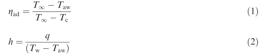
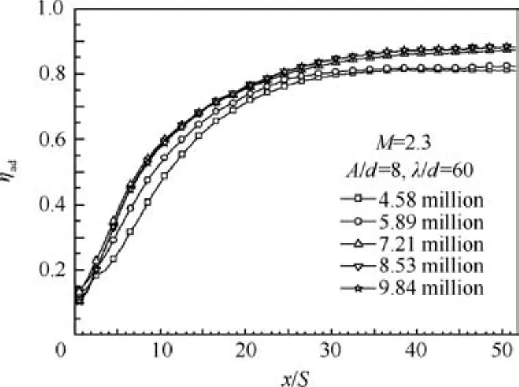
Fig.2 Grid independence test.

Either in the computations for determining the adiabatic film cooling effectiveness or in the computations for determining the convective heat transfer coef ficient,the computational boundaries for the primary flow inlet,the secondary flow inlet,and the out flow outlet are the same.


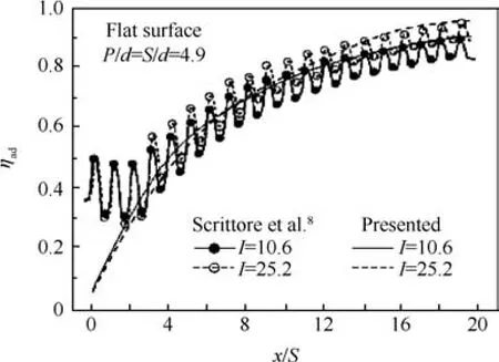
Fig.3 Validation of computational results for flat surface.
3.Results and discussion
3.1.Effect of blowing ratio
Fig.4 presents the effect of the blowing ratio on the adiabatic wall temperature distributions over the transverse corrugated surface with an amplitudeAof 8 mm and a wavelength k of 60 mm.
It is seen that the evolution of the film flow displays an obvious ‘developing” feature in front rows.In the front zone of an effusion cooling scheme,the adiabatic wall temperature corresponding to the first few rows is higher under a higher blowing ratio,which is in good agreement with results of discrete film cooling from early studies.26,27Under a higher blowing ratio,the coolant jet has a stronger penetration capacity,which will induce larger kidney vortices,as seen in Fig.5.These vortices are detrimental to film cooling because the mutual interaction between a vortex pair tends to lift the coolant jet off the surface.
Along the streamwise direction,film outflows from the front rows of multi-holes merge together gradually to form a relatively continuous film layer near the surface.Therefore,the adiabatic wall temperature decreases rapidly along the streamwise direction.Another notable feature is that the adiabatic wall temperature on the wavy valley of the transverse corrugated surface is relatively lower than that on the wavy peak.The contour cell corresponding to the lowest temperature on the wavy valley is enlarged in the streamwise direction with an increase of the blowing ratio.The wavy valley is helpful to accumulate the coolant outflow and thus builds up a thick film layer.By comparison,the varying gradient of the adiabatic wall temperature along the streamwise direction is greater under a higher blowing ratio.For multi-rows of film cooling holes,the jet spread capacity along the streamwise direction is stronger under a higher blowing ratio,leading to a rapider growth of the film layer,as seen in Fig.6.Besides,the vigorous film layer is provided with the ability of suppressing coolant jet penetration.Therefore,the cooling effectiveness of film jets originated from the downstream rows will be higher under a higher blowing ratio.
Fig.7 presents the effect of the blowing ratio on the laterally-averaged adiabatic film cooling effectiveness and heat transfer coefficient ratio distributions along the streamwise direction.
Here,the heat transfer coefficient ratioEgis defined as


Fig.4 Effect of blowing ratio on adiabatic wall temperature distributions.
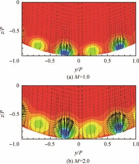
Fig.5 Cross-sectional velocity fields and temperature fields downstream from the 3rd row.
whereh0is the heat transfer coefficient without film holes on the surface.
The varying trend of the laterally-averaged adiabatic film cooling effectiveness,as seen in Fig.7(a),is the same as that revealed by previous research for effusion cooling over a flat surface.The film cooling effectiveness increases rapidly in the front rows of multi-holes where the film layer is undergoing a developing stage.Then it increases tardily in the middle rows of multi-holes until becoming constant once the effusion film layer is fully developed.It is also noted that the laterally-averaged adiabatic film cooling effectiveness in the front zone decreases with an increase of the blowing ratio.Fromx/S?12 or the 12th row on,the laterally-averaged adiabatic film cooling effectiveness is higher under a higher blowing ratio.Once the blowing ratio exceeds 2.0,the influence of the blowing ratio on the laterally-averaged adiabatic film cooling effectiveness seems very weak.
The jet injection produces increased turbulence levels inside the boundary layers.Increasing coolant injection typically produces increases in mixing and turbulence generation,which results in higher heat transfer coefficients.As expected,the heat transfer coefficient ratio increases with an increasing blowing ratio,as seen in Fig.7(b).The varying process seems to be divided as three stages.Firstly,the heat transfer coeff icient ratio increases rapidly along the streamwise direction.The turning point appears nearx/S=12.Then the heat transfer coefficient ratio varies tardily along the streamwise direction.Lastly,the laterally-averaged heat transfer coefficient ratio tends to be constant once the effusion film layer is nearly developed.
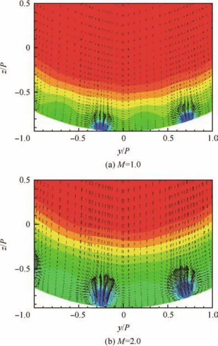
Fig.6 Cross-sectional velocity fields and temperature fields downstream from the 15th row.
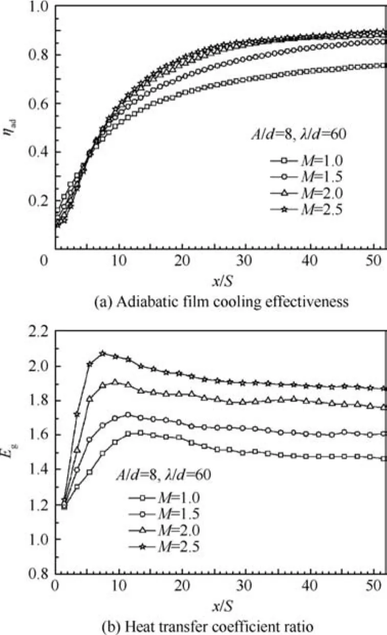
Fig.7 Effects of blowing ratio on laterally-averaged adiabatic film cooling effectiveness and heat transfer coef ficient ratio.
3.2.Effects of corrugation amplitude and wavelength
Fig.8 presents the effect of the corrugation geometry on the adiabatic wall temperature distributions over the transverse corrugated surface under a fixed blowing ratio of 2.3.For comparison,a flat surface is selected as the baseline case.
Relative to the baseline case(Fig.8(a)),it is found that the surface corrugation produces more obvious non-uniformity of temperature distributions in the lateral direction.For a fixed corrugation amplitude ofA=5 mm,the contour cell corresponding to the lowest temperature on the wavy valley is enlarged in the lateral direction with an increase of the corrugation wavelength,as seen from Fig.8(b)–(d).A similar trend is also true for the effect of the corrugation amplitude for a fixed corrugation wavelength of k=60 mm.As seen from Fig.8(d)–(f),the contour cell corresponding to the lowest temperature on the wavy valley is enlarged in the lateral direction with a decrease of the corrugation wavelength.In general,as the aspect ratio of the wavy corrugation increases,the contour cell corresponding to the lowest temperature on the wavy valley will be enlarged in the lateral direction.Either the corrugation amplitude or wavelength has relatively little in fluence on the distribution feature of the adiabatic wall temperature.
Fig.9 presents the effect of the corrugation amplitude on the local adiabatic film cooling effectiveness in the lateral direction.In the front zone of the effusion cooling surface,such as atx/S=5,the coverage of the film layer is relatively poor compared with that in the further downstream zone.The local adiabatic film cooling effectiveness is relatively low and the difference between the wavy peak and the wavy valley seems not obvious.With the film layer being developed,such as atx/S=15,the wavy valley of the corrugated surface is helpful to accumulate the coolant out flow and thus strengths the film extending capacity along the streamwise direction,which makes the local effusion cooling effectiveness on the wavy valley region to be higher than that of a flat surface,while the local effusion cooling effectiveness in the wavy peak region is signi ficantly lower than that of a flat surface.As the film layer develops further,such as atx/S=30,the film layer reaches nearly to the full development,and the difference between the wavy peak and the wavy valley behaves more obviously.
Figs.10 and 11 present the effects of the corrugation amplitude and wavelength on the laterally-averaged adiabatic film cooling effectiveness and heat transfer coefficient ratio distributions along the streamwise direction,respectively.
It is seen from Figs.10 and 11(a)that the surface corrugation has a relatively obvious influence on the laterally-averaged adiabatic film cooling effectiveness in the region where the effusion film layer is developed,but has little influence in the front region.The laterally-averaged adiabatic film cooling effectiveness increases as the aspect ratio of the wavy corrugation increases.The difference between the baseline case and the corrugated surface is more obvious under small aspect ratios.However,the corrugation geometry has an important influence on the laterally-averaged heat transfer coefficient ratio,even under larger aspect ratios,as seen in Figs.10 and 11(b).As the aspect ratio of the wavy corrugation increases,the laterally-averaged heat transfer coefficient ratio decreases.This trend is the same as the finding presented by Shinbo et al.16who concluded that the convective heat transfer in the case of a corrugated plate is larger than the one obtained for a flat surface,mainly due to the influence of the plate corrugations on the development of turbulence in the wall region.
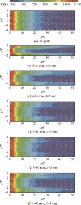
Fig.8 Effectofcorrugation geometryon adiabatic wall temperature distributions.
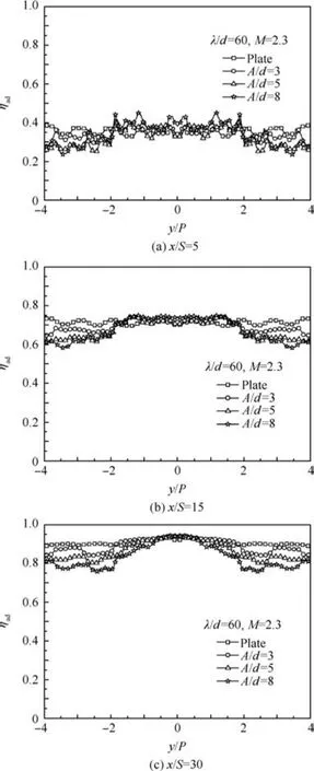
Fig.9 Effect of corrugation amplitude on local adiabatic film cooling effectiveness in lateral direction.
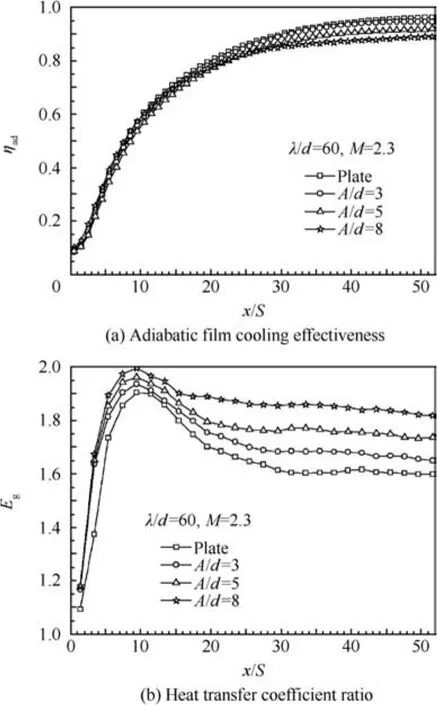
Fig.10 Effects of corrugation amplitude on laterally-averaged adiabaticfilmcoolingeffectivenessandheattransfercoefficientratio.
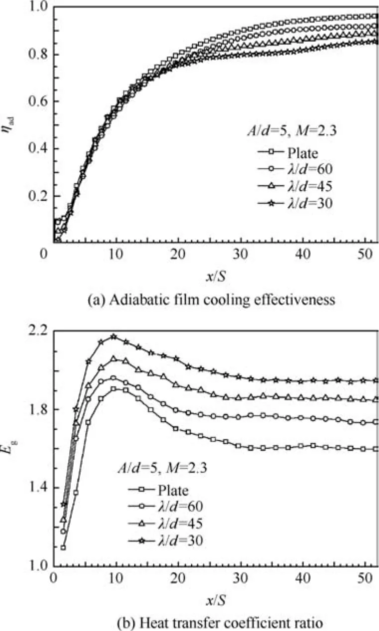
Fig.11 Effects of corrugation wavelength on laterally-averaged adiabatic film cooling effectiveness and heat transfer coefficient ratio.
4.Conclusions
Surface corrugation produces more obvious non-uniformity of the local adiabatic film cooling effectiveness distribution in the lateral direction relative to a flat surface.The adiabatic wall temperature on the wavy valley of a transverse corrugated surface is relatively lower than that on the wavy peak where the coolant outflow is more accumulated to build up a thick film layer.
Surface corrugation has a relatively obvious influence on the laterally-averaged adiabatic film cooling effectiveness in the region where the effusion film layer is developed,but has little influence in the front region.The laterally-averaged adiabatic film cooling effectiveness increases as the aspect ratio of the wavy corrugation increases.The difference between a flat surface and a corrugated surface behaves more obviously under a small aspect ratio of the wavy corrugation.
The corrugation geometry has an important influence on the laterally-averaged heat transfer coefficient ratio.The laterally-averaged heat transfer coefficient ratio decreases as the aspect ratio of the wavy corrugation increases.
1.Leger B,Miron P,Emidio JM.Geometric and aero-thermal influences on multi-holed plate temperature:application on combustor wall.Int J Heat Mass Transf2003;46(7):1215–22.
2.Cerri G,Giovannelli A,Battisti L,Fedrizzi R.Advances in effusive cooling techniques of gas turbines.Appl Therm Eng2007;27(4):692–8.
3.Krewinkel R.A review of gas turbine effusion cooling studies.Int J Heat Mass Transf2013;66(6):706–22.
4.Andrews G,Gupta M,Mkpadi M.Full coverage discrete hole film cooling:cooling effectiveness.J Turbo Jet Eng1984;2(3):199–212.
5.Andrews G,Gupta M,Mkpadi M.Full coverage discrete hole film cooling:the influence of hole size.J Turbo Jet Eng1997;2(3):213–25.
6.Bazdidi TF,Andrews G.Full coverage discrete hole film cooling:investigation of the effect of variable density ratio.J Eng Gas Turbines Power1994;116(3):587–96.
7.Bohn D,Moritz N.Influence of hole shaping of staggered multihole configurations on cooling film development.Reston:AIAA;2000.Report No:AIAA-2000–2579.
8.Scrittore JJ,Thole KA,Burd SW.Investigation of velocity profiles for effusion cooling of a combustor liner.ASME J Turbomach2007;129(3):518–26.
9.Yang CF,Zhang JZ.Influence of multi-hole arrangement on cooling film development.Chin J Aeronaut2012;25(2):182–8.
10.Yang CF,Zhang JZ,Yang WH.Effect of the holes array arrangement on the full coverage film cooling characteristics.J Aerospace Power2010;25(7):1524–9[Chinese].
11.Lin YZ,Song B,Li B,Liu G,Wu Z.Investigation of film cooling effectiveness of full-coverage inclined multihole walls with different hole arrangements.New York:ASME;2003.Report No:GT2003-38881.
12.Zhang C,Song B,Lin YZ,Xu Q.Cooling effectiveness of effusion walls with deflection hole angles measured by infrared imaging.Appl Therm Eng2009;29(5–6):966–72.
13.Ligrani P,Goodro M,Fox M,Moon HK,Ligrani P.Fullcoverage film cooling:film effectiveness and heat transfer coeff icients for dense and sparse hole arrays at different blowing ratios.ASME J Turbomach2012;134(6):061039-1-13.
14.Ligrani P,Goodro M,Fox M,Mook HK.Full-coverage film cooling:film effectiveness and heat transfer coefficients for dense hole arrays at different hole angles,contraction ratios,and blowing ratios.ASME J Heat Transfer2013;135(3),031707-1-14.
15.Andreini A,Facchini B,Picchi A,Tarchi L,Turrini F.Experimental and theoretical investigation of thermal effectiveness in multiperforated plates for combustor liner effusion cooling.ASME J Turbomach2014;136(9):091003-1-13.
16.Shinbo K,Koide Y,Kashiwagi T,Oguma M,Mizuno M,Funazaki K.Research of heat transfer of a liner for an afterburner.Reston:AIAA;1997.Report No:AIAA-1997-3005.
17.Champion JL,Deshaies B,Curtelin R,Desaulty M.Aerodynamical structure of the wall flow over a wavy surface partially cooled by air injection through multiperforations.Reston:AIAA;1999.Report No:AIAA-1999-1016.
18.Funazaki K,Igarashi T,Koide Y,Shinbo K.Studies on cooling air ejected over a corrugated wall:its aerodynamic behavior and film effectiveness.New York:ASME;2001.Report No:ASME 2001-GT-143.
19.Tang C,Chang HP,Mao JK.Numerical simulation of discrete holes on the longitudinal ripple wavy liner.J Eng Thermophys2007;28(3):487–9[Chinese].
20.Tang C,Chang HP.Numerical simulation of effusion holes on the longitudinal ripple heat shield.J Aerospace Power2009;24(1):18–24[Chinese].
21.Chang GQ,Chang HP,Chang H,Hu XD,Shan XQ.Experimental investigation on film cooling effectiveness of multi-hole at longitudinal wavy surface.J Aerospace Power2009;24(3):513–8[Chinese].
22.Chang F,Chang HP,Chang GQ,Tang C,Shan XQ.Numerical simulation of characteristic of film cooling on corrugated wall.J Eng Thermophys2009;30(2):2093–5[Chinese].
23.Harrison K,Bogard D.Comparison of RANS turbulence models for prediction of film cooling performance.New York:ASME;2008.Report No:ASME GT2008-50366.
24.Silieti M,Kassab AJ,Divo E.Film cooling effectiveness:comparison of adiabatic and conjugate heat transfer CFD models.Int J Thermal Sci2009;48(12):2237–48.
25.Yao Y,Zhang JZ,Tan XM.Numerical study of film cooling from converging slot-hole on a gas turbine blade suction side.Int Commun Heat Mass Transfer2014;52(2):61–72.
26.Schmidt DL,Sen B,Bogard DG.Film cooling with compound angle holes:adiabatic effectiveness.ASME J Turbomach1996;118(4):807–13.
27.Gritsch M,Schulz A,Wittig S.Adiabatic wall effectiveness measurements of film cooling holes with expanded exits.ASME J Turbomach1998;120(3):549–56.
8 October 2015;revised 25 November 2016;accepted 15 December 2016
Available online 21 February 2017
*Corresponding author at:College of Energy and Power Engineering,Jiangsu Province Key Laboratory of Aerospace Power System,Nanjing University of Aeronautics and Astronautics,Nanjing 210016,China.
E-mail address:zhangjz@nuaa.edu.cn(J.Zhang).
Peer review under responsibility of Editorial Committee of CJA.
 CHINESE JOURNAL OF AERONAUTICS2017年2期
- CHINESE JOURNAL OF AERONAUTICS的其它文章
- High-temperature tribological behaviors of a Cr-Si co-alloyed layer on TA15 alloy
- Analysis and control of the compaction force in the composite prepreg tape winding process for rocket motor nozzles
- Impact of lubricant traction coefficient on cage’s dynamic characteristics in high-speed angular contact ball bearing
- Variable stiffness design of redundantly actuated planar rotational parallel mechanisms
- Adaptive formation control of quadrotor unmanned aerial vehicles with bounded control thrust
- Constrained adaptive neural network control of an MIMO aeroelastic system with input nonlinearities