
Standing wave at dropshaft inlets*
2017-06-07 08:22:46JianhuaWu吳建華WeichenRen任煒辰FeiMa馬飛
水動(dòng)力學(xué)研究與進(jìn)展 B輯 2017年3期
Jian-hua Wu (吳建華), Wei-chen Ren (任煒辰), Fei Ma (馬飛)
College of Water Conservancy and Hydropower Engineering, Hohai University, Nanjing 210098, China, E-mail: jhwu@hhu.edu.cn
Standing wave at dropshaft inlets*
Jian-hua Wu (吳建華), Wei-chen Ren (任煒辰), Fei Ma (馬飛)
College of Water Conservancy and Hydropower Engineering, Hohai University, Nanjing 210098, China, E-mail: jhwu@hhu.edu.cn
2017,29(3):524-527
Standing waves occur frequently at the inlet due to the change of the flow direction from an approach channel to the dropshaft. The performance of the standing wave, characterized by the relative height, the location and the extent, is theoretically and experimentally investigated in the present paper. It is shown that the height of the standing wave decreases with the increases of the approach flow Froude number and the sub-channel number in the inlet, but increases with the increase of the curvature of the dropshaft. The errors of the expressions for the relative height, the location and the extent of the standing wave, are 9.7%, 7.8% and 13.1%, respectively, as compared with the experimental data.
Dropshaft, height, location, extent, standing wave
The dropshafts, as the elements of the urban underground tunnel system for the rain drainage, carry the discharge from the land surface to the underground tunnel. For the four types of dropshaft inlets, i.e., the circular, the scroll, the spiral, and the tangential types, the standing waves occur frequently at the inlet due to the change of the flow direction from an approach channel to the inlet[1,2]. There are some investigations about the standing wave in channel bends, however, they are all based on a relatively small curvature, such as in the range of 0.07-0.25[3-6].
Based on the experimental results, Hager suggested that the maximum height of the standing wave is related to both the approach flow Froude number and the dropshaft diameter for the scroll-type inlets under the condition of supercritical approach flows[7]. For the same type inlets, the experiments by Motzet and Valentin showed that, the height of the standing wave increases with the increase of the discharge of the approach flow until the hydraulic jump occurs and the flow is turned into the subcritical flow from the supercritical flow[8]. Giudice et al.[9]presented a method of forming the subcritical flow through a negative steplocated along the supercritical approach channel for the modification of the standing wave in the inlet.

Fig.1 Definition sketch of geometric and hydraulic parameters and standing wave of dropshaft inlet
In this paper, we present an estimation method for the standing wave, and on the basis of the theoretical analyses and physical model experiments, we evaluate the performance of the standing wave in the inlets under the various conditions of the approach flow Froude number, the curvature and the sub-channel number of a dropshaft inlet, for the maximum curvature of 0.60.
Figure 1 shows the definition sketch of the geometric and hydraulic parameters and the standing wave of a dropshaft inlet. The origin of the cylindrical coordinate system ( )rzj is at the center of the plane view of a dropshaft, and the connection location and its elevation between the approach flow channel and the dropshaft inlet are the start points of the coordinatesj and z, respectively. In this figure, B and b are the widths of the approach flow channel and the subchannel, respectively, and = /n Bb, is the number of sub-channels.r1is the radius of the dropshaft and is a constant, while r2is the radius of the ventilation duct. hoand voare the depth and the average velocity of the approach flow, respectively (Fig.1(a)). The standing wave is characterized by its heightMh, the location jMof the maximum elevation and the extentjL, and hM=zM- ho, jL=j1- jo, where zMis the maximum elevation of the standing wave, and joand 1j are the locations of the start and the end of the standing wave at the level of ho, respectively (Fig.1(b)).
The features of the standing wave are a function of the geometric and hydraulic parameters of the dropshaft inlet
According to the dimensional analysis theory, we have

where Fro= vo/(g ho)0.5, is the Froude number of the approach flow, and ra= B/r1, is the relative curvature. Equation (2) implies that the features of the standing wave are a function ofoFr,ar and n. Experimental procedure is outlined for variable parameters that affect the features of the standing wave.
The experiments are conducted in the High Speed Flow Laboratory, Hohai University, Nanjing, China. The experimental setup consists of a pump, an approach conduit, a large feeding basin, a test model, and a flow return system. The test model includes an approach flow channel, a dropshaft and a tail water channel (Fig.2).
Fig.2 Experimental setup
Table 1 lists the cases and the geometric parameters of the models. The cases are divided into two sets. The cases M11-M13 are designed to study the effects of ra, while the cases M11-M31 for the effects of n.
Figure 3 shows the photos of the standing wave for the various Froude numbers of the approach flow. Clearly, the intensities of the standing wave, characterized by hM, jMand jL, decrease with the increase of Fro.
Figure 4 shows the variation of /hM1r withoFr for variousar. Also, it is noticed that, the larger the value of ra, the larger will be the value of hM/r1for the same Fro. By means of the multiple linear regression method and based on the experimental data, we can obtain the results expressed by Eq.(2), shown in Figs.5-7. Thus, we have:

They are valid for 1.29 £ Fro£ 7.50, 1 £ n£ 3 and 0.30 £ ra£ 0.60 according to the conditions of Table 1. Comparing with the experimental data, the errors of Eqs.(3)-(5) are 9.7%, 7.8% and 13.1%, respectively.
This paper studies theoretically and experimentally the performance of the standing wave at the dropshaft inlet under the conditions listed in Table 1. /hM1r,jMand jLare all in an inverse proportion withFroand n, but in a direct proportion with raon the basis of Eqs.(3)-(5).

Table1 Cases and geometric parameters for models
Fig.3 Side views of the standing wave for M11
Fig.4 Variation of hM ×r1- 1with Froat various ra
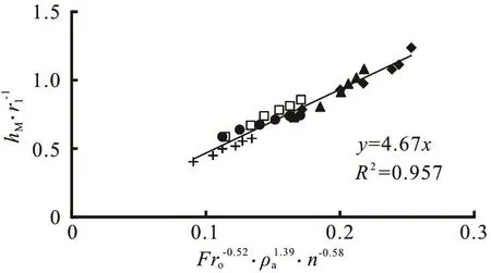
Fig.5 Variation of
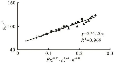
Fig.6 Variation of
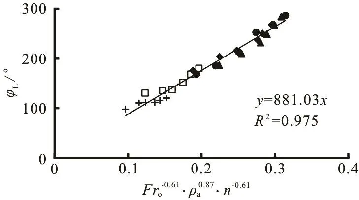
Fig.7 Variation of
[1] Giudice G. D., Gisonni C. Vortex dropshaft retrofitting: Case of Naples city (Italy) [J]. Journal of Hydraulic Research, 2011, 49(6): 804-808.
[2] Giudice G. D., Gisonni C., Rasulo G. Design of a scroll vortex inlet for supercritical approach flow [J]. Journal of Hydraulic Engineering, ASCE, 2010, 136(10): 837-841.
[3] Reinauer R, Hager W. H. Supercritical bend flow [J]. Journal of Hydraulic Engineering, ASCE, 1997, 123(3): 208-218.
[4] Solari L, Dey S. Marchi’s research on supercritical flow in tight bends and backwater effects [J]. Journal of Hydraulic Engineering, ASCE, 2015, 142(2): 02515004.
[5] Tian J. N. Water flow behaviors of channel bend in middle sized radius and big bend angle of curvature [J]. Journal of Xian University of Technology, 2000, 16(1): 28-32(in Chinese).
[6] Wu Y. F., Wu C., Li J. et al. Water surface superelevation in sharp open-channel bends [J]. Journal of Sichuan University, 2006, 38(6): 38-42(in Chinese).
[7] Hager W. H. Vortex drop inlet for supercritical approaching flow [J]. Journal of Hydraulic Engineering, ASCE, 1990, 116(8): 1048-1054.
[8] Motzet K. M., Valentin F. Efficiency of a vortex chamber with horizontal bottom under supercritical flow [C]. 9th International Conference on Urban Drainage. Portland, USA, 2002, 1-11.
[9] Giudice G. D., Gisonni C., Rasulo G. Design of a scroll vortex inlet for supercritical approach flow [J]. Journal of Hydraulic Engineering, ASCE, 2010, 136(10): 837-841.
10.1016/S1001-6058(16)60765-5
March 20, 2017, Revised April 15, 2017)
* Project supported by the National Natural Science Foundation of China (Grant No. 51479057).
Biography:Jian-hua Wu (1958-), Male, Ph. D., Professor
猜你喜歡
青年文學(xué)家(2024年31期)2024-12-31 00:00:00
故事作文·低年級(jí)(2022年1期)2022-02-03 10:35:17
水動(dòng)力學(xué)研究與進(jìn)展 B輯(2018年5期)2018-10-27 09:11:40
故事作文·低年級(jí)(2018年9期)2018-09-17 18:35:32
故事作文·低年級(jí)(2018年6期)2018-07-04 16:39:22
水動(dòng)力學(xué)研究與進(jìn)展 B輯(2018年2期)2018-05-14 01:43:30
讀寫算·小學(xué)低年級(jí)(2017年4期)2017-04-15 16:44:51
作文周刊·小學(xué)一年級(jí)版(2016年29期)2017-03-02 13:02:00
水動(dòng)力學(xué)研究與進(jìn)展 B輯(2016年5期)2016-12-06 08:15:46
 水動(dòng)力學(xué)研究與進(jìn)展 B輯2017年3期
- 水動(dòng)力學(xué)研究與進(jìn)展 B輯的其它文章
- Shedding frequency of sheet cavitation around axisymmetric body at small angles of attack*
- Numerical analysis of bubble dynamics in the diffuser of a jet pump under variable ambient pressure*
- Shock waves and water wing in slit-type energy dissipaters*
- Optimal contract wall for desired orientation of fibers and its effect on flow behavior*
- Numerical investigation of the time-resolved bubble cluster dynamics by using the interface capturing method of multiphase flow approach*
- The influence of nonlinear shear stress on partially averaged Navier-Stokes (PANS) method*