
Shock waves and water wing in slit-type energy dissipaters*
2017-06-07 08:22:46GuobingHuang黃國兵HanHu胡晗CaihuanWang王才歡LanDu杜蘭
水動力學(xué)研究與進展 B輯 2017年3期
Guo-bing Huang (黃國兵), Han Hu (胡晗), Cai-huan Wang (王才歡), Lan Du (杜蘭)
Changjiang River Scientific Research Institute, Wuhan 430010, China, E-mail: huanggb@mail.crsri.cn
Shock waves and water wing in slit-type energy dissipaters*
Guo-bing Huang (黃國兵), Han Hu (胡晗), Cai-huan Wang (王才歡), Lan Du (杜蘭)
Changjiang River Scientific Research Institute, Wuhan 430010, China, E-mail: huanggb@mail.crsri.cn
2017,29(3):504-509
The slit-type energy dissipater (STED) is widely used in hydraulic projects of high water head, large discharge, and narrow river valley, thanks to its simple structure and high efficiency. However, the water wing caused by the shock waves in the contraction section of the STED may bring about harmful effects. A coefficient is introduced for the application of Ippen?s theory in the STED. The expression of the coefficient is experimentally obtained. Simplified formulas to calculate the shock wave angle and the water wing scope are theoretically derived, with relative errors within 5%.
Slit-type energy dissipater (STED), shock wave, water wing, hydraulic modelling
Introduction
The slit-type energy dissipater (STED) changes the trajectories of a nappe by using a contraction flip bucket[1,2]. The flow energy is greatly dissipated in this process and then the erosion of the downstream channel can be relieved[3,4]. Because of its simple structure and high efficiency, the STEDs were widely used in hydropower projects with high water head, large discharge, and narrow river valley. The energy dissipations in many large scale hydraulic projects in China, such as the Longyangxia dam[5], the Ertan dam[6], the Shuibuya dam[7], and the Geheyan dam[8]were greatly relieved by the application of the STEDs.
The STEDs were studied theoretically and experimentally from the aspects of the energy dissipation[9], the structure safety[10], the flow surface in the channel[11], the characteristics of pressure and cavitation[12], the shape of the nappe[13], and the scouring effect of the downstream riverbed[14]. Zhang and Wu (1989), Dai and Yu (1992) experimentally observed the movement and extension features of the nappe,and proposed estimated formulas for the flow profile in the contraction section. Wu et al.[15]suggested empirically the conversion conditions of the nappe forms, and experimentally investigated the behaviour of the flow choking[16]. The estimated formulas for the nappe maximum width and the locations of slit-type flip buckets were presented by Liu et al.[17]. Huang et al.[18]developed a method to calculate the dynamic water pressure in the contraction section of the STED.
As a special hydraulic phenomenon, the water wing of the STED may harm the stability of the bank and the safety of downstream buildings[19]. In the hydraulics prototype observation of the Geheyan project, it was found that, the water wing diffused transversely, and scoured the side bank slope. And the operation of the flood-releasing surface outlets on both sides was then limited. The results of the model test of the Shiubuya project indicate that, the collision of the shock waves in the contraction section causes part of the water detached from the main flow and scours the river bank. However, previous studies paid little attention to the harmful effects caused by the water wings. Hence, it is necessary to study the formation mechanism and the movement features of the shock waves and the water wings.
In the present study, physical model experiments and theoretical analyses are conducted to reveal the internal relationship between the shock wave and the movement characteristics of the water wing.
1. Experimental set-up and methodology
The experimental set-up consists of a high pressure water tank, a sloping flume, a STED structure, and a downstream pool. The high pressure water tank is 10.0 m high to provide an adequate flow of suitable water head. Through a Plexiglas-made sloping flume the flow goes into the STED structure. The sloping flume is 3.2 m long, 0.2 m wide and 2.0 m high.
Figure 1 is the definition sketch of the flow through a STED, in which α is the bucket angles of the STED, L is the length of the contraction section, and B and b are the widths before and after the contraction section, respectively, resulting in a contraction ratio of /bB.
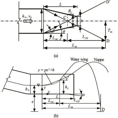
Fig.1 Definition sketch for flow through a STED
The origin of the coordinate system (,)xy is at the beginning of the STED bottom. e is the height from some base level to the bottom, C is the colliding point of the shock waves produced by the contraction sidewalls, g is the maximum angle of the water wing to the horizontal level at the Point C, D is the position of the water wing at the base level,MT is the distance from the Point D to the coordinate axis x, LOCis the distance from the origin of the coordinate system to the Point C, and LCDis the distance between C and D in the direction of the coordinate axis x, with LM=LOC+LCD. Therefore, the scope of the water wing in the directions of the coordinate axes x and y could be expressed asML andMT .0h and v0are the depth and the average velocity of the approach flow, respectively, and then we have the Froude number of the flow.
Table 1 lists the cases and geometric parameters of the STED models with various bucket angles and contraction ratios.0Fr varies from 4.10 to 5.90 in the present work.
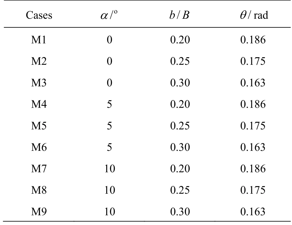
Table 1 Geometric parameters of STED models
2. Flow observation
Figure 2 and Fig.3 show the flows in the top and side views. It could be clearly noticed that the flow is contracted transversely and extended longitudinally while passing through the STED. Especially, the shock waves occur from the beginning of the STED due to the contraction effects of the side walls. There are strong water wings over the top and the two sides of the main nappe due to the collision of the shock wave effects. Those water wings may impact the banks and then bring about harmful effects. So, it is necessary to estimate the scope of the water wings.
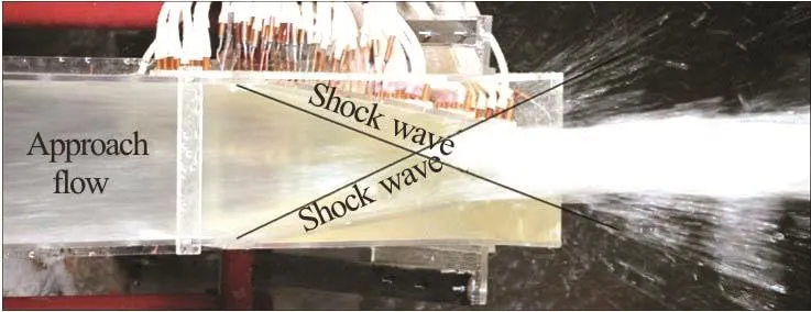
Fig.2 (Color online) Top view of flow through a STED
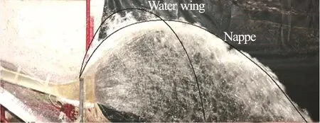
Fig.3 (Color online) Side view of flow through a STED
3. Shock waves
Ippen put forward an ideal shock wave theory based on the assumption of the hydrostatic pressure distribution over the depth, with the basic equations for the shock wave[20]. Figure 4 shows the plane viewof a shock wave caused by the sidewall deflection. The approach flow along AO with the depth0h and the velocity0v is deflected by a sidewall OB with a deflection angle q, then the depth and the velocity of the approach flow become1h and1v while crossing a jump line OC. The angle of the jump line OC is defined as the shock wave angle b, and the angle from the sidewall OB to the jump line OC is defined as j.
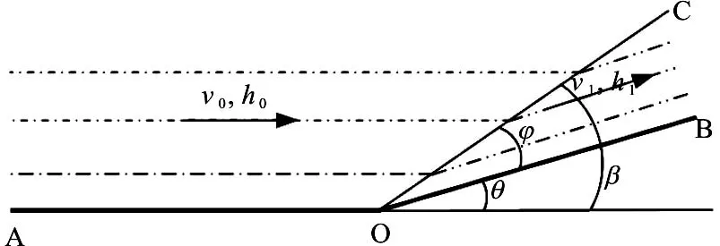
Fig.4 Sketch of the shock wave
Based on the continuity and momentum relationships, combined with the geometry of the velocity vectors, the angle of the shock wave b can be determined by
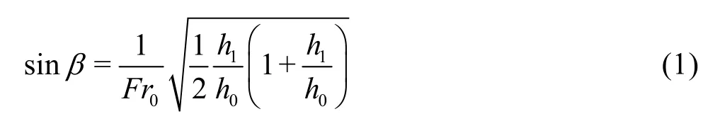
where0Fr is the approach flow Froude number.
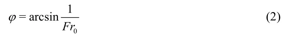
Ippen’s formula was simplified by Hager et al.[21,22]and Liu et al.[17], j could be simply calculated by
However, because of the sharp bend sidewalls and the narrow width of the surface, in the STEDs the assumption of the hydrostatic pressure distribution over the depth will no longer be valid. So Eq.(2) would result in a large deviation, and need to be modified in the the application to the STEDs.
It is assumed that,
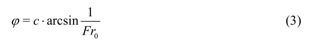
where c is a correction coefficient, which depends on the geometric and hydraulic parameters of the STEDs.
The influencing factors include the bucket anglea, the sidewall deflection angle q, and the Froude number of the approach flow0Fr. An orthogonal analysis indicates that, only the sidewall deflection angle q, and the Froude number of the approach flow Fr0have significant influences on the coefficient c.
The relationship between the coefficient c and the Froude number of the approach flow0Fr for different deflection angles q is plotted in Fig.5.
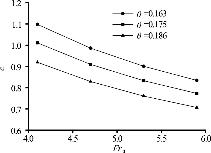
Fig.5 Variation of c with 0Fr
According to the results of the least-squares method, c can be calculated as
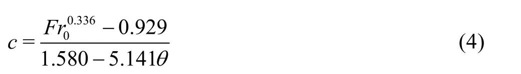
As a result, the shock wave angle becomes
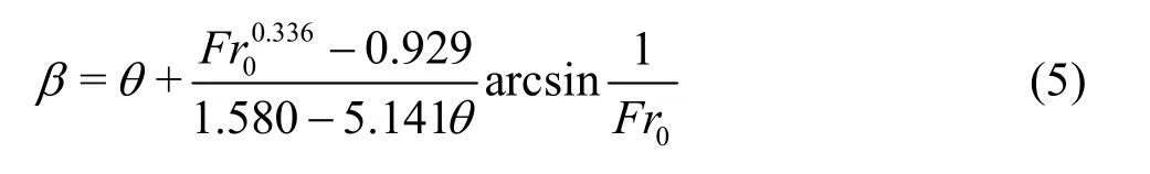
Equation (5) is applicable to the STED with the deflection angle 0.163 £ q£ 0.186 and the Froude number of the approach flow 4.10 £ Fr0£ 5.90. As compared with the experimental results in Table 2, the maximum relative error of Eq.(5) is 0.27%, and the average relative error is 0.15%.
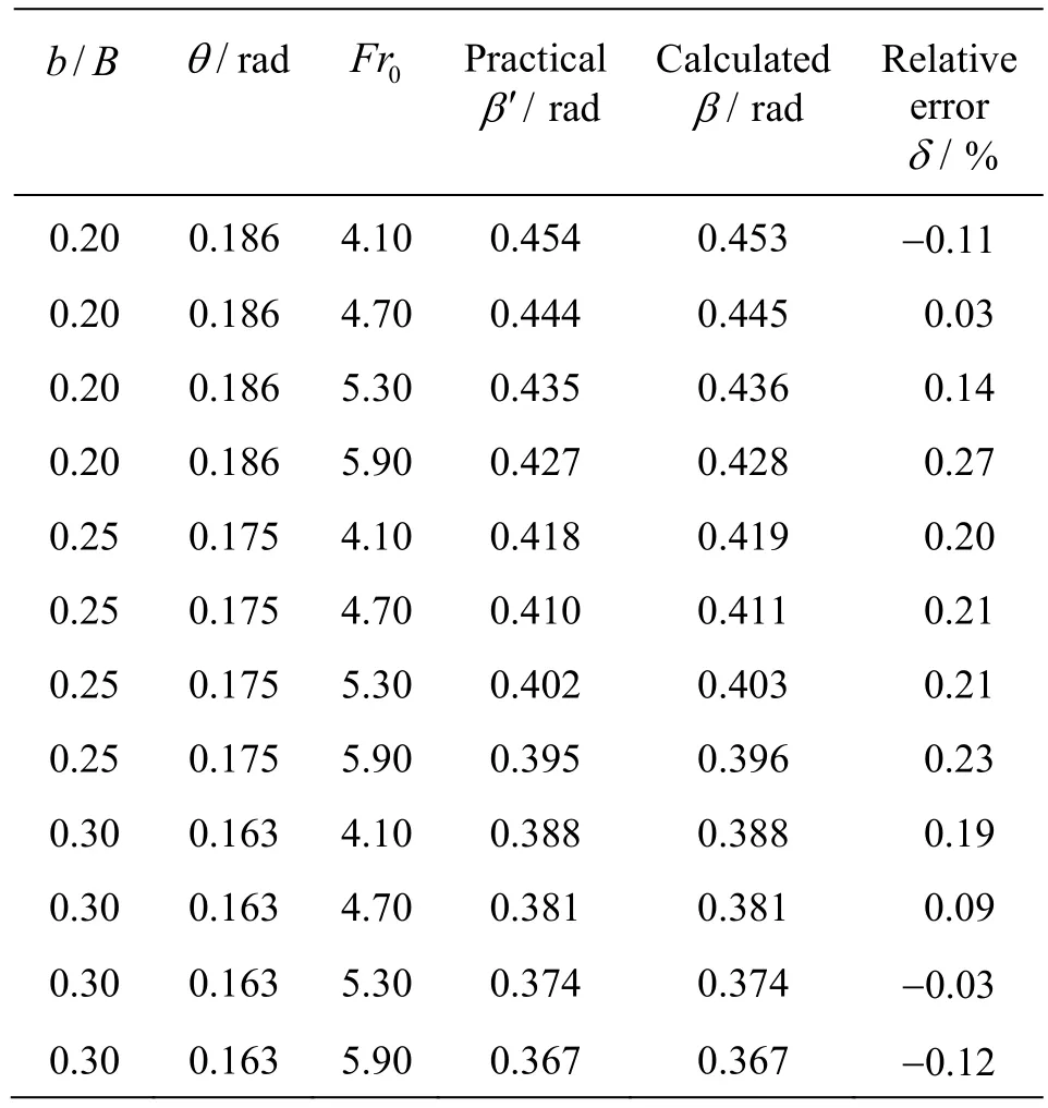
Table 2 Calculation errors of shock waveb
4. Water wing
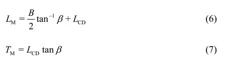
The scope of the water wing could be estimated from the values ofML andMT . According to the geometry relationships, as depicted in Fig.1, we have
The shape of the water wing could be regarded as a trajectory of the projectile motion. SoCDL could be calculated based on the projectile motion theory.
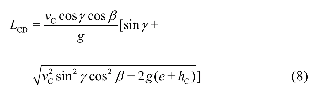
where,Cv, g andCh are the velocity, the angle of departure, and the depth at the shock wave collision Point C, respectively, g is the gravitational acceleration. Therefore, the values ofCv, a andCh need to be determined.
4.1 Calculation forCv
The value ofCv could be calculated based on Ippen’s theory. The velocity after the shock wave is determined by the angle of the shock wave.
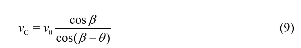
where0v is the velocity of the approach flow before the shock waves.
4.2 Calculation forCh
The depth at the shock wave collision point could be obtained from the continuity equation,
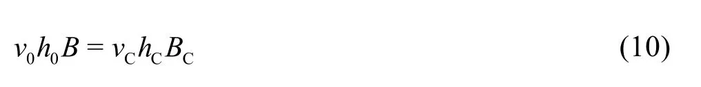
whereCB is the width of the contraction section at the shock wave collision point.
Then,
4.3 Calculation for g
According to the experimental results (as demonstrated in Fig.6), the flow surface along the central line could be approximately expressed as the shape of a parabolic function

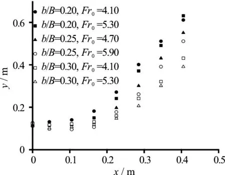
Fig.6 Flow surface along the central line under various conditions
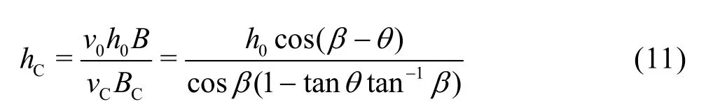
As defined above, the coordinates of the collision Point C are (LOC,hC). So
Being substituted into Eq.(12), the parabolic function turns out to be
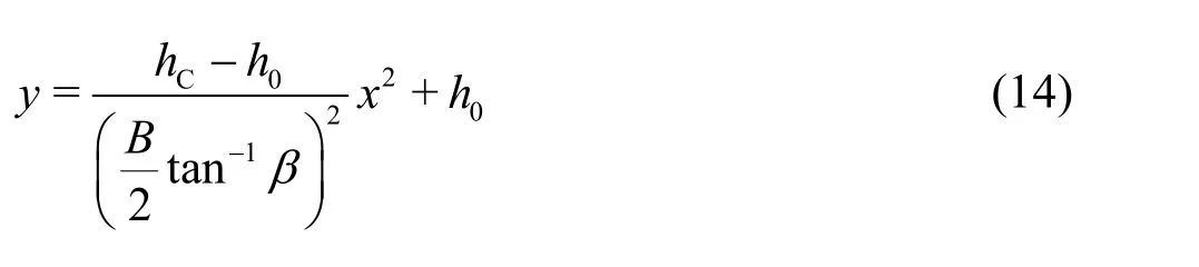
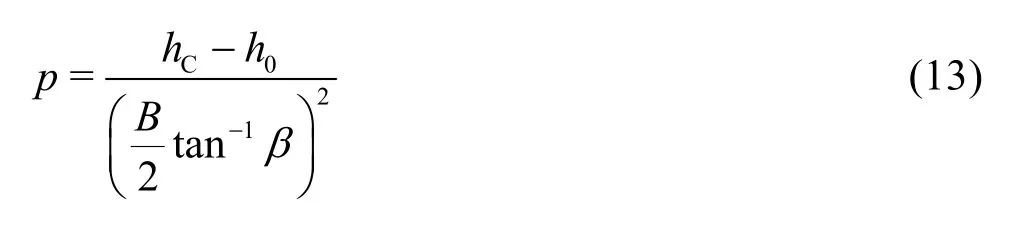
From the derivative of Eq.(14) at C (LOC,hC), the slope at the collision point is obtained as
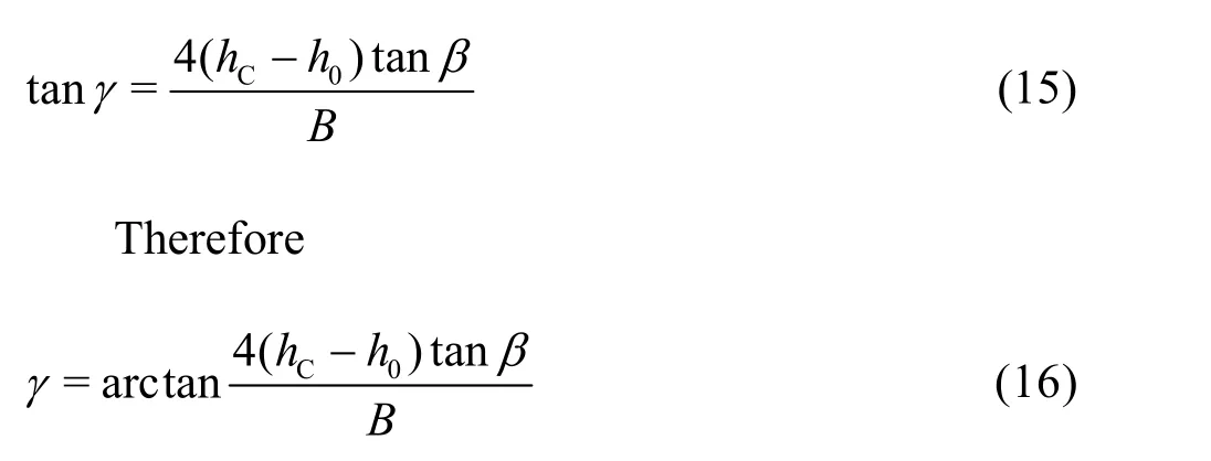
To validate Eqs.(6) and (7), the calculation results Sc(LMand TM) are compared to the experimentally determined area Seof the rainfall caused by the water wing in Fig.7 under various conditions. But, it is difficult to define the boundary of the water wing. In some studies[16]the rainfall with an intensity stronger than 500 mm/h is defined as the heavy rainfall according tothe prototype observation experience. Hence, after the conversion, the prototype typical rainfall intensity contour of 500 mm/h is defined as the affected scope of the water wing.
Fig.7 Comparison between experimental water wing area and the calculated results
The maximum relative errors ofML andMT are 4.4% and 4.7%, respectively, while the average relative errors are 3.0% and 2.6%.
5. Conclusion
With Ippen?s theory, a coefficient is introduced in order to correct the deviation of the shock wave angle to the sidewall for the present STED. The expression of the coefficient is experimentally obtained. On the basis of this coefficient, a method is proposed to estimate the scope of the water wing, including the length and the width. Comparison with the experimental data demonstrates that the relative errors of the present method are 4.4% and 4.7% in the directions of the length and the width of the water wing, respectively.
Acknowledgement
This work was supported by the Basic Research Foundation of Changjiang River Scientific Research Institute (Grant Nos. CKSF2017011/SL, CKSF2017055/SL and CKSF2014047/SL).
[1] Cheng C. T., Shen J. J., Wu X. Y. et al. Operation challeges for fast-growing China’s hydropower systems and respondence to energy saving and emission reduction [J]. Renewable and Sustainable Energy Reviews, 2012, 16(5): 2386-2393.
[2] Li N. W., Xu W. L., Zhou M. L. et al. Experimental study on energy dissipation of flood discharge in high arch dams without impact of jets in air [J]. Journal of Hydraulic Engineering, 2008, 39(8): 927-933(in Chinese).
[3] Xiao X. B. Summary of application of slot dissipator for high dam energy dissipation and its development [J]. Design of Hydroelectric Station, 2004, 20(3): 76-81(in Chinese).
[4] Chen Z. R., Chen Y. D., Huang G. B. Research of configuration of narrow opening ski jump spillway and estimation of longitudinally extended width of jet [J]. Journal of Yangtze River Scientific Research Institute, 2002, 19(4): 11-14(in Chinese).
[5] Xie S., Wu Y., Chen W. New technology and innovation on flood discharge and energy dissipation of high dams in China [J]. Journal of Hydroelectric Engineering, 2016, 47(3): 324-336(in Chinese).
[6] Liu M. N. Prototype observation of the ski shaped discharge spillway of Dongjiang hydropower plant [C]. Drainage Engineering and High Speed Flow Information Network the Fourth Conference Proceeding. Chengdu, China, 1994(in Chinese).
[7] Ma J., Zhang Y., Zheng S. Experimental study on the characteristics of flow in spillway system with differential slotted flip bucket terminal structures for Shuibuya hydropower project [J]. Journal of Hydroelectric Engineering, 2007, (3): 93-99(in Chinese).
[8] Sha H. F., Zhou H., Chen H. L. Numerical simulation of 3-D flow formed by slit-type energy dissipater for midlevel outlets [J]. Journal of Hydraulic Engineering, 2006, 37(5): 625-629(in Chinese).
[9] Kuzmanovic V., Savic L., Milovanovic B. Ski jump design [J]. Water Management, 2010, 163(10): 523-527.
[10] Alias N. A., Mohamed T. A., Ghazali A. H. et al. Impact of takeoff angle of bucket type energy dissipater on scour hole [J]. American Journal of Applied Sciences, 2008, 5(2): 117-121.
[11] Avinash Panwar H. L. T. Hydraulic energy dissipaters–A review [J]. International Journal of Scientific Engineering and Technology, 2014, 3(4): 400-402.
[12] Reyes-Salazar A., López-Barraza A. Effectiveness of energy dissipaters type friction on the reduction of the inelastic seismic responses of moment steel frames [J]. Journal of Engineering Computing and Architecture, 2008, 2(1): 1-14.
[13] Chen H. Y., Xu W. L., Deng J. et al. Numerical simulation and experimental study on the characteristics of slit-type energy dissipater in high arch dam [J]. Journal of Hydraulic Engineering, 2012, 43(4): 445-451(in Chinese).
[14] Wang R., Liu H., Nie Y. et al. Application of curved slittype flip bucket at Maerdang hydropower station[J]. Journal of Hydroelectric Engineering, 2015, 34(2): 85-90(in Chinese).
[15] Wu J. H., Ma F., Yao L. Hydraulic characteristics of slittype energy dissipaters [J]. Journal of Hydrodynamics, 2014, 26(1): 86-93.
[16] Wu J. H., Wan B., Ma F. et al. Flow choking characteristics of slit-type energy dissipaters [J]. Journal of Hydrodynamics, 2015, 27(1): 159-162.
[17] Liu Y., Ma F., WU J. H. Shock waves and jet width of slittype flip bucket [J]. Advances in Science and Technology of Water Resources, 2014, 34(3): 20-29(in Chinese).
[18] Huang Z. M., He X. H., Zhu H. H. et al. Analysis of configuration lay out and hydro dynamic pressure characteristics of slit-type bucket [J]. China Rural Water and Hydropower, 2006, (5): 69-72(in Chinese).
[19] Zhang Y., Wang J. Study on application of slit-bucket energy dissipater to multi-tunnel combined spillways [J].Journal of Hydroelectric Engineering, 2015, 34(2): 112-117(in Chinese).
[20] Ippen A. T. Gas-wave analogies in open channel flow [C]. Proceedings 2nd Hydraulics conference. Bulletin 27, Iowa, USA: University of Iowa, 1943.
[21] Harger W. H., Bretz N. V. Discussion of “Simplified design of contractions in supercritical flow” by Terry W. Strum [J]. Journal of Hydraulic Engineering, ASCE, 1987, 113(3): 422-427.
[22] Harger W. H., Schwalt M., Jimenez O. Supercritical flow near an abrupt wall deflection [J]. Journal of Hydraulic Research, 1994, 32(1): 103-118.
10.1016/S1001-6058(16)60762-X
May 12, 2016, Revised February 22, 2017)
* Project supported by the National Nature Science Foundation of China (Grant Nos. 51279013, 51379020 and 51509015), the National Key R & D Program of China (Grant No. 2016YFC0401900).
Biography:Guo-bing Huang (1963-), Male, Master, Professor
Han Hu, E-mail: smith_hu@qq.com

- 水動力學(xué)研究與進展 B輯的其它文章
- Standing wave at dropshaft inlets*
- Shedding frequency of sheet cavitation around axisymmetric body at small angles of attack*
- Numerical analysis of bubble dynamics in the diffuser of a jet pump under variable ambient pressure*
- Optimal contract wall for desired orientation of fibers and its effect on flow behavior*
- Numerical investigation of the time-resolved bubble cluster dynamics by using the interface capturing method of multiphase flow approach*
- The influence of nonlinear shear stress on partially averaged Navier-Stokes (PANS) method*