
Numerical research on the performances of slot hydrofoil*
2015-02-16 06:43:32WEIQun魏群CHENHongxun陳紅勛ZHANGRui張睿
水動(dòng)力學(xué)研究與進(jìn)展 B輯 2015年1期
關(guān)鍵詞:張睿
WEI Qun (魏群), CHEN Hong-xun (陳紅勛), ZHANG Rui (張睿)
1. Shanghai Institute of Applied Mathematics and Mechanics, Shanghai University, Shanghai 200072, China
2. Institute of Civil Engineering, Nanchang University, Nanchang 330031, China, E-mail: qunwei@shu.edu.cn
Numerical research on the performances of slot hydrofoil*
WEI Qun (魏群)1,2, CHEN Hong-xun (陳紅勛)1, ZHANG Rui (張睿)1
1. Shanghai Institute of Applied Mathematics and Mechanics, Shanghai University, Shanghai 200072, China
2. Institute of Civil Engineering, Nanchang University, Nanchang 330031, China, E-mail: qunwei@shu.edu.cn
(Received December 21, 2013, Revised July 3, 2014)
The paper presents an numerical study of the hydraulic and cavitating characteristics of a slot hydrofoil at the angle of incidence ofo
hydrofoil, performance, optimal design, cavitation inhibition
Introduction
Hydrofoil is the key factor of axial-flow pump’s design, foil section has direct effect on the performance. The high efficiency working area of axial-flow pump is very narrow, with the change of external operation environment it may work on low efficiency condition, companying by greater hydraulic loss and system instability. To improve the performance of axial-flow pumps at low flow rate, Chen applied slotted technology[1]on 791 hydrofoil and Zhang designed a slot hydrofoil[2]by hydraulic optimization design, which applied in the design of an axial-flow pump. It’s validated that the efficiency of this axial pump with slot blades increases at low flow rate by numerical and experimental means.
Cavitation can give rise to hydraulic performance deterioration, noise, vibration and erosion damage, so cavitating character is another indicator evaluating the performance of a pump. In present paper, the research aiming at cavitating characteristics of this slot hydrofoil at the angle of incidence of 6° will be performed.
Cavitation flow around a hydrofoil is often a multiphase flow associated with turbulence, unsteady flows and phase change, etc. Many researches have been carried out to simulate the cavitation flow and noticeable progresses have been made in recent years. A common approach to modeling cavitation is the homogeneous flow theory, where the mixture density is introduced and only one single set of mass and momentum equations is solved. Different approaches have been proposed to generate the variable density field. One of those is adopting arbitrary barotropic equation of state for density[3-5]. Another approach is transport equation model(TEM), fulfilled by a supplementary equation or the simplified Rayleigh-Plesset equation controlling the convection of the vapor[6-10]. TEM models have similar format but with different source terms. Frikh et al.[11]analyzed the influence of different models on the simulation of cloud cavitation on 2-D foil section, the results showed a large resemblance between most of models and modifying parameters change the cavity shape and structure. Many experiences[12-14]have proved that CFD simulation can be used to analyze the cavitating behavior successfully with coupling suitable cavitation and turbulence models.
In this paper, the cavitating behavior of the slothydrofoil will be investigated by a homogeneous model on comparison with 791 hydrofoil for 6oattack angle. Furthermore, to achieve good hydraulic and cavitation performances, optimal research of the slot hydrofoil will be conducted with Ansys Workbench12.1, in which the cavitation index is introduced as another optimization goal besides hydraulic parameters.
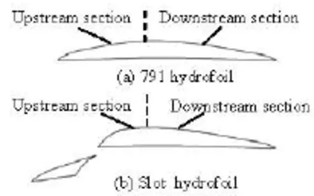
Fig.1 Geometry of hydrofoils
1. Geometry of hydrofoil
The research object of this work is an optimal slot hydrofoil based on 791 hydrofoil (C =0.158 m). 791 hydrofoil (Fig.1(a)) was verified to have good hydraulic performance and cavitation resistence through production practice, which was proposed by Guan[15]. The slot hydrofoil (Fig.1(b)) was designed by Zhang through optimization for maximum lift-drag ratio with constraint of lift.
2. Numerical methods
In order to figure out the cavitation performance of the slot hydrofoil, numerical simulations were carried out. The numerical model solved the unsteady Navier-Stokes equations, coupled with SST turbulence model and the Bakir[16]Rayleigh Plesset cavitation model with automatic near-wall treatment which can automatically switch from wall functions to a low-Re near wall formulation as the mesh is refined. The saturation pressure was 3 574 Pa. All simulations were done with general purpose CFD code ANSYS CFX 12.1. Equations were discretized on the element-based finite-volume, the second-order high resolution scheme and second-order backward Euler scheme were used separately for the advection term and transient term. Unsteady simulations were carried out with the initial values of corresponding steady simulation results.
2.1 Validation of the numerical methods
Leroux et al.[17]had taken researches on NACA 66 mod hydrofoil by both experimental and numerical means. To verify the validity of numerical methods, the adopted numerical methods were used to simulate the cavitation flow around NACA66 mod hydrofoil at two same conditions to experiments done by Leroux. Geometry was simplified to 2-D problem witho>6 attack angle, and the grid was generated with structured grid with 27 006 nodes (Fig.2). Figure 3 shows the predicted pressure distribution on the suction side of the hydrofoil for σ=1.41, in which the pressure distribution agrees well with the experimental data. For =1.25σ, the calculation results display that the cavity undergoes the growth and shedding process with main frequency of 3.57 Hz, and the experimental value is 3.625 Hz. From the above, it can be concluded that the numerical methods adopted in this paper can correctly simulate the cavitation flow around hydrofoil.
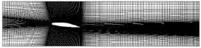
Fig.2 General view of the grid around NACA 66 mod foil
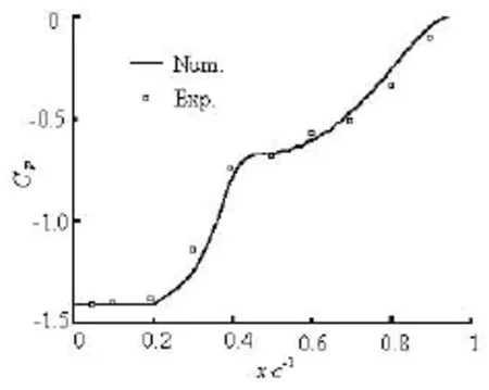
Fig.3 Pressure distribution on suction side of NACA 66 (α= 6o, σ=1.41)
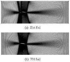
Fig.4 General view of the grid around foils
2.2 Boundary condition , grid and time resolution
The geometry was simplified to 2-D problem, which is fixed within a 11C long and 4C wide square cross test section. The slot foil was designed to improving the hydraulic performance at low flow rate, so the angle of incidence of the foil in this research is setto beo6. The mesh were generated with H type structured grids, show in Fig.4. The boundary conditions for incompressible flows were applied: fixed inlet velocity and specified outlet pressure according to the cavitation number, the non-slip wall was set for the wall boundary condition, free stream velocity was 6 m/s.
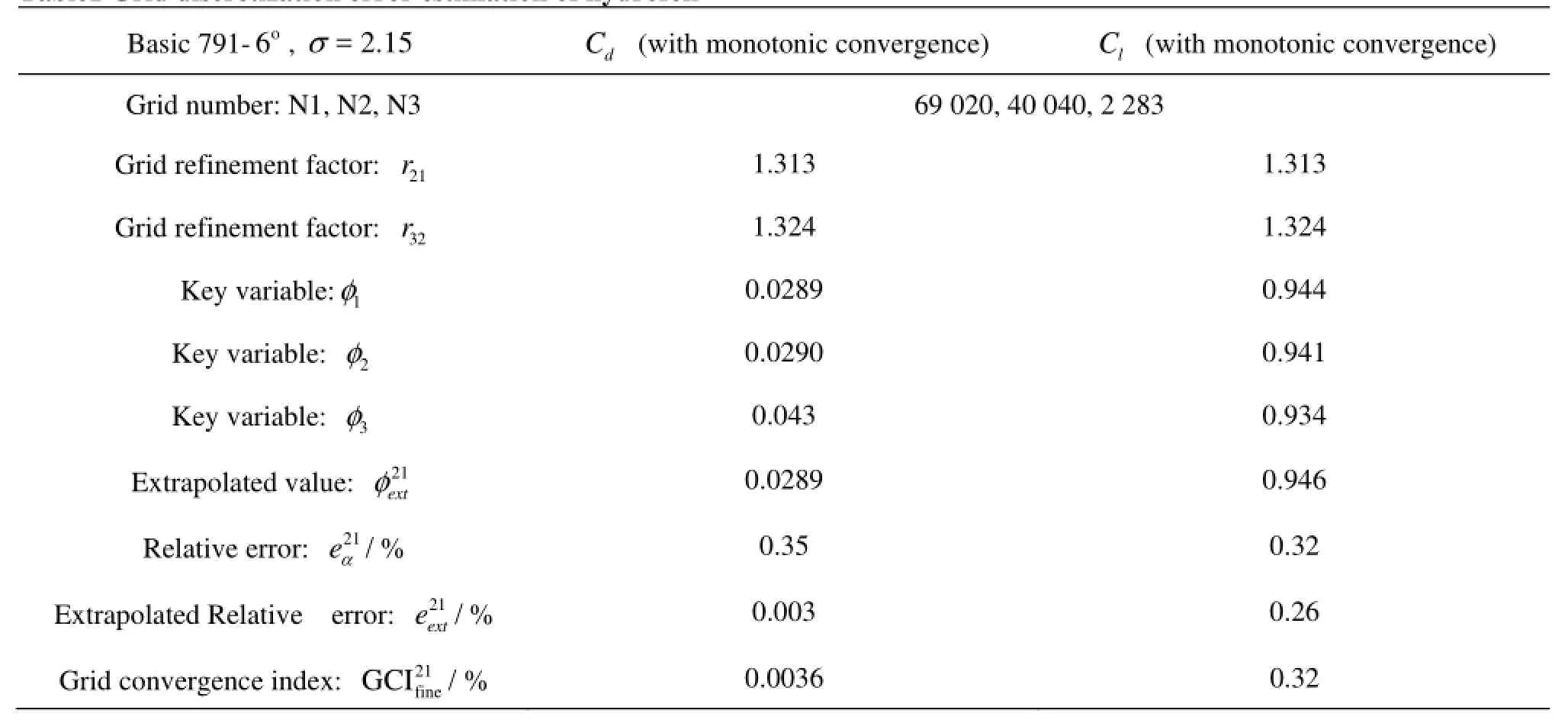
Table1 Grid discretization error estimation of hydrofoil
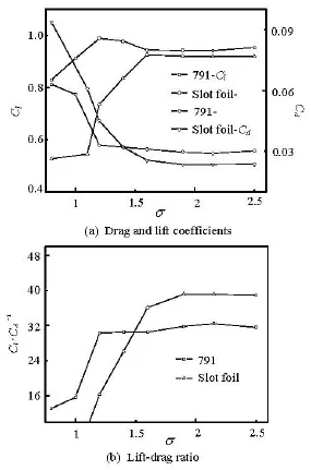
Fig.5 Drag and lift coefficients, lift-drag ratio for various cavitation number α=6o
In order to get grid-convergent results, a criterion based on the Richardson Extrapolation Technique[18]was used to improve the grid resolution, in which the truncation error and accuracy were systematically evaluated. Three sets of grids were generated, the drag coefficient and lift coefficient were chosen as the key variables. The values were based on the steady simulation at a non-cavitation condition, showed in Table 1. The grid monotonic convergence results were obtained according to the key variables’ variation. Both relative errors were below 0.5%, and the grid convergence index was estimated to be less than 0.5%. Thus grid N1 was used as the final computation which was referenced as the base of the grid generation of the slot hydrofoil.
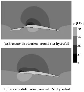
Fig.6 Pressure distribution around the hydrofois =2.5σ
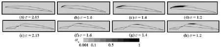
Fig.7 The contour of void fraction on two hydrofoils versus various σ
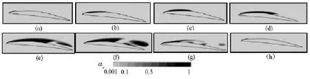
Fig.8 Instantaneous void fraction evolution during one cycle for 791 hydrofoil =0.8σ
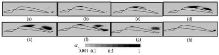
Fig.9 Instantaneous void fraction evolution during one cycle for slot hydrofoil =0.8σ
In transient simulation, the time duration and time step were referenced based on the NACA66 hydrofoil. The time step was 2×10⁻⁴s, the total time was 60Tref, where Tref=Lref/Vrefwith Lref=0.158 m being the chord length and Vref=6 m/s being the inlet flow velocity.
3. Cavitation performance comparison
Figure 5 shows the lift, drag coefficient and liftdrag ratio varying with cavitation number. Before cavitation occurring, the lift-drag ratio of the slot hydrofoil is over 20% higher than the original 791 hydrofoil, with lift coefficient lower less than 4%. Figure 6 shows that the pressure difference between the two sides of the slot hydrofoil is a little less than that of the 791 hydrofoil, so the lift force decrease slightly. But the drag force decreases notablely because of the attack angle and position of the vice hydrofoil.
The contour of void fraction on two type hydrofoils at different cavitation number are showed in Fig.7. For 791 hydrofoil, cavitation occurred at the leading edge of the suction side from σ=1.25, and both the lift force and drag force decrease slightly, which induces the increasing of the lift-drag ratio in a narrow range. With σ decreasing, cavitation develops, the lift force remains steady and the drag force increases slightly, which results in little reduce of the lift-drag ratio. For σ=1.6-1.2the cavity generated on the suction side grows bigger, both the lift and drag force increase simultaneously, the lift-drag ratio remains constant. For σ=2.15-1.2cavity length is less than 0.5C, the closure of the cavity experienced small variations, but the general length varies little and the cavity can be stated as stable. For =1.0σ the cavity grows larger than 0.5C, the length of vapor varies and vapor cloud sheds periodically, and the lift and drag force deteriorate sharply. Figure 8 displays a periodical vapor evolution process for =0.8σ. It is found that a cavity generates at the leading edge of the suction side of foil, when the cavity length reaches up to about 0.6C, the reentrant jet appears which cuts the cavity partially from the bottom. With the reentrant flow developed, the vapor break off completely and causes shedding vapor cloud, then the reentrant flow begins to spread forward upstream which causes the residual vapor to contract and when it crosses the limit of the cavity, the residual cavity collapse. The vapor cloud sheds at a frequency of 5.57 Hz.
For slot hydrofoil, cavitation occurs for =1.9σ,since then the lift and drag force deteriorate rapidly. When σ deduced from 1.9-1.2, cavitation developed quickly, the cavity grows larger and keeps so called“stable”. From 1.2σ≤, the lift and drag force degrades sharply. For 1.0σ≤, cavitating behavior gets unstable and cycle cavity developing can be observed. Figure 9 displays the vapor clouds shedding process for =0.8σ. Results show that the reverse flow occurs at nearly 0.5C from the trailing edge which cuts the cavity partially from the bottom either, then followed by the growing of both two parts. With the reentrant flow continuously developing, two parts connecting to top of each other break off and vapor cloud shedding occurs, when the reentrant flow begins to flow upstream forward which results in the contraction of the residual vapor and collapse finally. The frequency of periodical vapor cloud shedding is 8.626 Hz, higher than that of 791 hydrofoil.
From above, it shows that when cavitation occurs, even the cavity is much thinner and smaller on the slot hydrofoil than that on 791 hydrofoil at the same cavitation number, the performances of slot hydrofoil deteriorate sharply(Fig.7) yet. For 791 hydrofoil, performances doesn’t get worse until the cavity length is greater than 0.5C and the cavity area extends to the downstream section (negative slope) of the suction side, when cavitating behavior became unstable with reentrant flow and vortex occurring. For slot hydrofoil, the low pressure area and cavity locates in the downstream area of the suction side and the performance damage appears from the beginning of cavitation. So analysis supports that the bigger upstream slope of the main foil of slot hydrofoil accounts for the bad cavitation inhibition, that is small upstream slop of suction side would suppress the hydraulic performance loss for cavitation.
4. Optimization research of slot hydrofoil
According to above results, it’s obvious that the form of splitting curve is critical to cavitation performance. To improve the hydraulic and cavitation performance, the curve will be ameliorated, and optimization research will be conducted to find an optimum position of the vice foil.
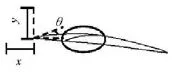
Fig.10 The sketch of new slot hydrofoil
4.1 Geometry and optimization problem
A new slot hydrofoil is displayed in Fig.10, with smaller upstream slope of main hydrofoil. Numerical optimization calculation was carried out on Workbench of Ansys 12.1 by transferring the vice hydrofoil relative to the main one. The design variables are x, y, θ referenced, where x was the horizonal distance, y was the vertical distance, θ was the rotating angle relative to the horizontal direction. The
objective functions were lift-drag ratio (Cl/Cd), lift coefficient (Cl) and cavitation index at cavitating condition. Wherein cavitation index is the volume average of water vapor of a specific domain, which is consisted of negative slope area (downstream) of the suction side of the main foil, because the cavity on upstream part of the suction side doesn’t damage the performance until it extends to the downstream section.
The optimization problem reads:
Multiple objective functions
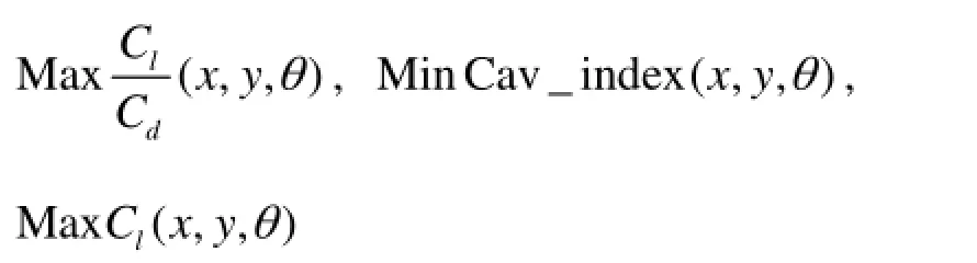
Wherein the importance of Min (Cav-index) is set higher, the importance Max (Cl/Cd) is set lower, and the value of lC was set not less than791lC as hard constraint.
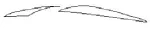
Fig.11 Geometry of the optimized slot hydrofoil
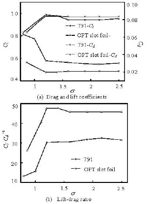
Fig.12 Drag and lift coefficients, Lift-Drag ratio for various cavitation number α=6o
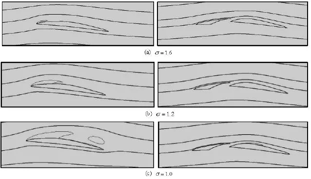
Fig.13 Contrast figures of streamline and void fraction isosurface (α=0.1) around hydrofoil
The constraint condition

4.2 Optimization method and results
Custom plus sampling type was used in design of experiments with total 100 samples, standard response-full 2-nd order polynomials type was set for response surface, and screening optimization method was adopted in the Goal Driven Optimization. The final optimized design result is displayed in Fig.11 (x=-0.043825 m , y=-0.004735 m , θ=4.6).
4.3 The cavitation behavior of the optimized slot hydrofoil
Numerical simulations had been conducted from non-cavitating condition to cavitating condition for several σ ato6 attack angle. Figure 12 shows that for the optimized foil, the lift-drag ratio is 40% higher, the lift coefficient is 2% higher and the drag coefficient is 29.3% lower than those of 791 foil at non-cavitating condition.
Figure 13 displays the streamlines around the main foil and the vapor isosurface (αv=0.1), it shows that the streamline is much more fitted because of the guidance of the vice foil. So even great vapor cavity generates for 791 hydrofoil when =1.2σ, no vapor occurs on the slot hydrofoil. When =1.0σ, cavitating behavior around 791 hydrofoil is unstable and vapor cloud shedding occurred, instead a little steady vapor cavity generates on the downstream of suction side of the slot hydrofoil. But even steady and relative weak cavitation on the negative section of the suction side of optimal slot foil destroys the performance. Comparing to the slot foil by Zhang, the lift-drag ratio is 16% higher, the lift coefficient is 5% higher and the drag coefficient is 10% lower at non-cavitating condition, and the cavitation occurs at much lower σ. In general, not only the lift, drag and the lift-drag ratio are more superior, but also the cavitation inhibition is more excellent.
5. Conclusion
Numerical researches were carried out on the performances of a slot hydrofoil ato6 attack angle. Computations indicates that the hydraulic performance of the slot hydrofoil is better than 791 hydrofoil at non-cavitating condition, however when small cavity occurs, the hydraulic performances deteriorated sharply. Instead, for 791 hydrofoil the cavity always locates on the upstream part of the suction side, only when cavity length developing up to over 0.5C and extending to the negative slope section of the foil, the hydraulic performance starts to decline. It can be deduced that the big upstream slope of the suction side of the main hydrofoil accounts for the damage of performance when the cavity generating at the negative slope of the suction side. To improve the performance of this slot hydrofoil, new splitting curve was designed, and computational optimization of vice foil location was carried out on the Workbench of Ansys 12.1. Through numerical simulation, it’s verified thatthe optimized slot hydrofoil achieves better hydraulic and cavitation performances at certain incident angle.
[1] Chen Hong-xun, HUO Cong-cong and LIU Wen-mei. Study on control of multi-element airfoil based on CFD[J]. Journal of Drainage and Irrigation Machinery Engineering, 2012, 20(5): 513-516(in Chinese).
[2] ZHANG Rui. Research on the stall and cavitation flow characteristics and the performance improvement of Axial-flow pump[D]. Doctral Thesis, Shanghai, China: Shanghai University, 2014(in Chinese).
[3] VENTIKOS Y., TZABIRAS G. A numerical method for the simulation of steady and unsteady cavitating flows[J]. Computers and Fluids, 2000, 29(1): 63-88.
[4] WANG Guo-yu, FANG Tao and CAO Shu-liang et al. Numerical modeling of unsteady viscous cavitation flows[J]. Journal of Engineering Thermophysics, 2004, 25(5): 783-789(in Chinese).
[5] EDWARDS J. R., FRANKLIN R. K. Low-diffusion flux-splitting method for real fluid flows with phase transitions[J]. AIAA Journal, 2000, 38(9): 1624-1633.
[6] SINGHAL A. K., ATHAVALE M. M. and LI H. Mathematical basis and validation of the full cavitation model[J]. Journal of Fluids Engineering, 2002, 124(3): 617-624.
[7] ZWART P. J., GERBER A. G. and BELAMRI T. A two-phase flow model for predicting cavitation dynamics[C]. The Fifth International Conference on Multiphase Flow. Yokohama, Japan, 2004.
[8] SCHNERR G. H., SAUER J. Physical and numerical modeling of unsteady cavitation dynamics[C]. The Fourth International Conference on Multiphase Flow. New Orland, USA, 2001.
[9] KUNZ R. F., BOGERA D. A. and TINEBRINGA D. R. et al. A preconditioned Navier-Stokes method for twophase flows with application to cavitation prediction[J]. Computers and Fluids, 2000, 29(8): 849-875.
[10] SENOCAK I., SHYY W. Interfacial dynamics-based modeling of turbulent cavitating flows, Part I: Model development and steady-state computations[J]. International Journal for Numerical Methods of Fluids, 2004, 44(9): 975-995.
[11] FRIKHA S., COUTIER-DELGOSHA O. and ASTOLFIJ. A. Influence of the cavitation model on the simulation of cloud cavitation on 2D foil section[J]. International Journal of Rotating Machinery, 2009, 2008: 146234.
[12] ZHAO Jing, WEI Ying-jie and ZHANG Jia-zhong et al. Effect of various turbulence models on simulated results of cavitating flow[J]. Engineering Mechanics, 2009, 26(8): 233-238(in Chinese).
[13] HUANG Biao, WANG Guo-yu and ZHANG Bo et al. Assessment of cavitation models for computation of unsteady cavitating flows[J]. Journal of Ship Mechanics, 2011, 15(11): 1195-1202(in Chinese).
[14] HAO Zong-rui, WANG Le-qin and WU Da-zhuan. Numerical simulation of unsteady cavitating flow on hydrofoil[J]. Journal of Zhejiang University: Engineering Science, 2010, 44(5): 1043-1048(in Chinese).
[15] GUAN Fan-xing. Modern pump technical manuals[M]. Beijing, China: Aerospace press. 1998(in Chinese).
[16] BAKIR F., REY R. and GERBER A. G. et al. Numerical and experimental investigations of the cavitating behavior of an inducer[J]. International Journal of Rotating Machinery, 2004, 10(1): 15-25.
[17] LEROUX J. B., ASTOLFI J. A. and BILLARD J. Y. An experimental study of unsteady partial cavitation[J]. Journal of Fluids Engineering, 2004, 126(1): 94-101.
[18] CELIK B. I., GHIA U. and ROACHE P. J. et al. Procedure for estimation and reporting of uncertainty due to discretization in CFD applications[J]. Journal of Fluids Engineering, 2008, 130(7): 078001.
10.1016/S1001-6058(15)60462-0
* Project supported by the National Natural Science Foundation of China (Grant No. 51379120), the Science and Technology Plan of Zhejiang Province (Grant No. 2011C11068), and the Shanghai Program for Innovative Research Team in University.
Biography: WEI Qun (1978-), Female, Ph. D., Lecturer
CHEN Hong-xun, E-mail: chenhx@shu.edu.cn
6. Results indicate that the performance of this slot hydrofoil is better than the original hydrofoil at non-cavitation condition, but deteriorates sharply once cavitation occurred. To improve the performance, a new splitting scheme was put forward and optimization research was carried out at the same indicent angle, numerical results show that the optimized slot hydrofoil achieves better hydraulic and cavitation performances.
猜你喜歡
閱讀(快樂(lè)英語(yǔ)中年級(jí))(2023年6期)2023-05-24 01:20:32
閱讀(快樂(lè)英語(yǔ)中年級(jí))(2023年4期)2023-05-11 21:37:51
小主人報(bào)(2022年7期)2022-08-16 06:59:28
小主人報(bào)(2022年5期)2022-04-01 01:12:02
新教育論壇(2019年13期)2019-09-10 03:26:53
Communications in Theoretical Physics(2018年8期)2018-08-02 07:35:40
快樂(lè)作文·低年級(jí)(2017年11期)2017-12-06 08:35:18
校園英語(yǔ)·下旬(2017年11期)2017-10-31 16:21:08
小資CHIC!ELEGANCE(2016年25期)2016-11-15 19:18:28
中學(xué)生數(shù)理化·七年級(jí)數(shù)學(xué)人教版(2016年2期)2016-05-30 21:20:57
 水動(dòng)力學(xué)研究與進(jìn)展 B輯2015年1期
- 水動(dòng)力學(xué)研究與進(jìn)展 B輯的其它文章
- Flow choking characteristics of slit-type energy dissipaters*
- Ferrofluid measurements of bottom velocities and shear stresses*
- Study of errors in ultrasonic heat me*ter measurements caused by impurities of water based on ultrasonic attenuation
- Wave-current i*mpacts on surface-piercing structure based on a fully nonlinear numerical tank
- 3-D numerical investigation of the wall-bounded co*ncentric annulus flow around a cylindrical body with a special array of cylinders
- Numeri*cal simulation of 3-D water collapse with an obstacle by FEM-level set method