
Modeling and Experimental Verification for a Novel Wireless Power Transmission System via Electromagnetic Resonant Coupling
2014-11-25 09:23:48ZhangXianYangQingxinZhangXinLiYangJinLiangZhangPengcheng
電工技術(shù)學報 2014年2期
Zhang Xian Yang Qingxin Zhang Xin Li Yang Jin Liang Zhang Pengcheng
(Tianjin Key Laboratory of Advanced Technology of Electrical Engineering and Energy Tianjin Polytechnic University Tianjin 300387 China)
1 Introduction
Taking the advantage of non-radiative near-field area to achieve power transmission wirelessly,EM coupling resonance technology has currently received a lot of attention for greatly expansion in transmission distance[1-3].It adds to greater freedom to power acquisition when compared to induction power transmission,and is more secure and simplified compared to electromagnetic(EM) radiation power transmission.However,simplifications of some mutual inductance models cause error when describing high-frequency characteristics[4-6].Especially there is certain blindness for the lack of accurate theoretical support in design of an actual system.
In this paper,the time domain solution of power exchange between two resonators is acquired.Two key prerequisites of strong coupling are deduced by discussing the angular frequency,mode coupling factor and quality factor.Then the overall transmission efficiency,power transmission ability and the maximum power of the load are analyzed in-depth.Through a coupled system consisting of two disc-type resonators,the measured values have ±2.5% error compared with theoretical ones.Moreover,the optimal working distance calculated by present model is consistent with experimental value which indicates the accuracy of the theoretical analysis.
2 Prerequisites of power exchange between resonators
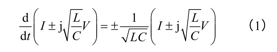
It is easy to describe the general laws of wave phenomena such as optical nonlinearity,light waves and sound waves interaction according to coupled mode theory[7,8].For a LC oscillating circuit,the first order Hamiltonian form of circuit equations can be obtained by basic circuit theory,which is shown as Eq.1.
Then,energy exchange between resonators can be described by two decoupled differential equations as[9,10]
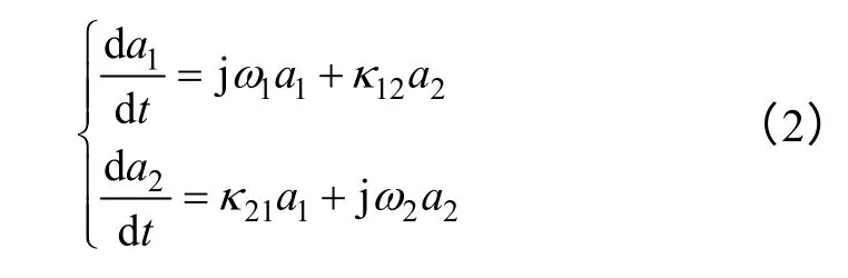
Where a1and a2are forward rotation mode of resonators whose second norm contains energy dimension;ω1,2are natural resonant angular frequency;κ12and κ21are mode coupling factors.For passive lossless system,energy exchange existed between modes and meet conservation for overall energy.Any changes of the oscillation mode need to go through natural resonant periods under weak coupling circumstance,so it comes to a1(t)=A1(t)exp[0.5j(ω1-ω2)t],where A1(t) is a slowly varying function about time.Assuming initial conditions as Eq.3 when t=0.In time domain,solutions can be expressed as Eq.4.
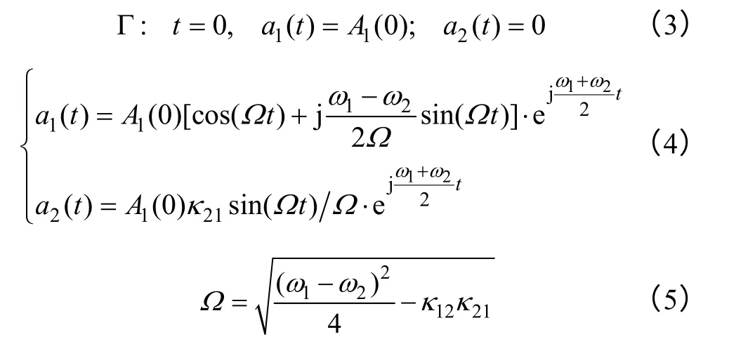
Their two eigenvalues are λ12=±Ω.So resonators cannot obtains the maximum energy exchange unless ω1=ω2which is the first prerequisite.For lossy coupling system,modified resonant angular frequency can be expressed as Eq.6 and eigenvalues are as Eq.7 by Taylor expansion,when Q is large enough.
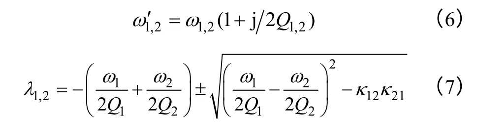
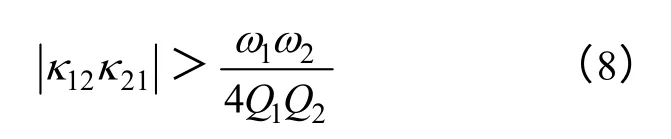
If there is a sustained increase in oscillation,it must meet the condition that root item take a positive sign and is larger than previous items in bracket.So the second prerequisite is shown as Eq.8 after simplification.
Energy exchange relationship between resonators in normalization is shown as Fig.1 in which |a1|2,|a2|2and |a1+a2|2indicate energy of resonator 1,2 and overall system.Presence of quality factor Q makes the overall energy decays exponentially.Reason of attenuation in linear system includes Joule loss and radiation loss which can be expressed as absorption and radiation of Q value.When angular frequencies differ greatly as Fig.1a,most of energy stored in resonator 1,and the receiving end gets very limited energy which is a direct result of decline in transmission power and overall efficiency.As shown in Fig.1b with ω1=ω2but different mode coupling factor,though there is almost 100% energy exchange,it cannot keep sustaining or disappearing through several cycles.As soon as the two requirements are met,it is working under the strong coupling state in which the proportion of energy exchange reaches 100% theoretically,as shown in Fig.1c.
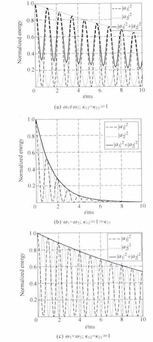
Fig.1 Schematic of normalized energy exchanging
3 System performance analysis
3.1 Function of power transmission capability
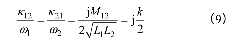
For linear coupled system,due to constraint of energy conservation,relationship between mode coupling factor and circuit coupling coefficient k can be obtained after the comparison with circuit equations as[9,11]
When system has symmetrical structure and operates in vicinity of resonant point,there is
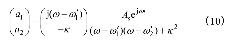
If it meets energy transmission prerequisite in previous section,received energy of resonator 2 is
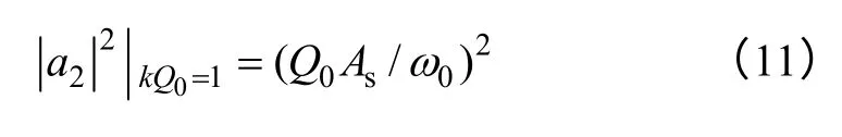
When coupled coils placed coaxially,coupling coefficient k is a function of radius r and spacing distance d as[12].
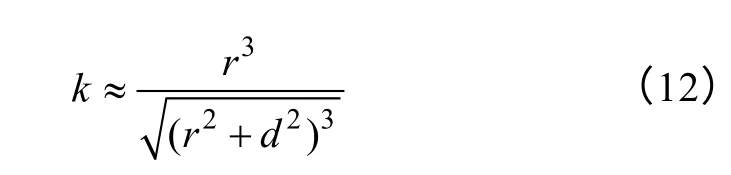
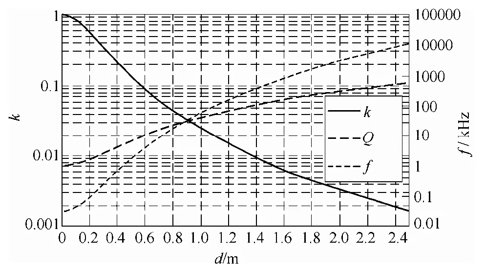
Fig.2 Power transfer capability of EM coupling system
As long as the desired power of receiving end is less than Eq.11,system power transmission capacity curve can be obtained,as shown in Fig.2 in which k,Q and f are three groups of longitudinal axis coordinates,and are shown on left and right sides,respectively.There are always three intersections when drawing a line perpendicular to horizontal axis.Physical significance of three intersection points is the minimum quality factor and resonant frequency required that enables system to work in resonance when changing distance to obtain different coupling coefficient.From what has been mentioned above,we can look up for the maximum operation distance in the figure when the designed resonant frequency and quality factor are determined.
3.2 The maximum power conditions of load
A general structure of EM coupling system is shown in Fig.3 where transmitting end is composed of source coil and resonator a1while the receiving end is composed of resonator a2and device coil.Power on two resonators is acquired by means of induction and exchanges between each other through EM resonantly coupling.Va1,2,Ia1,2,La1,2,Ca1,2and Ra1,2are equivalent voltage,current,inductance,capacitance and resistance of resonator a1,2;LS,Dand RS,Dare equivalent inductance and resistance of source coil and device coil respectively;VSis source voltage;RLis load resistance;MS1,M2Dare mutual inductance between corresponding components.In addition,it is assumed that energy between resonators is exchanged only through M12,so coupling coefficient kijis defined as:
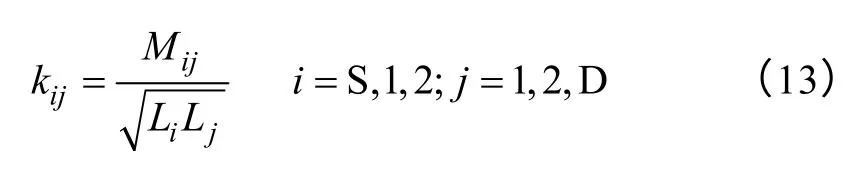
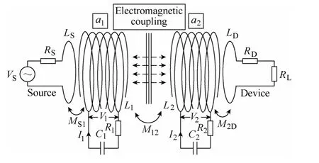
Fig.3 Structure of EM resonant coupling system
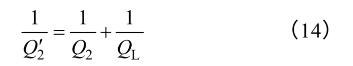
If k2Dis small enough,equivalent quality factor 2Q' of receiving end can be expressed as
Quality factor reflects the ratio of EM energy stored in circuit when in resonance and energy consumed in a cycle.Energy consumption comes from the resonator itself and load resistance.Therefore when load coil resistance RDis ignored,active power on the load PLis
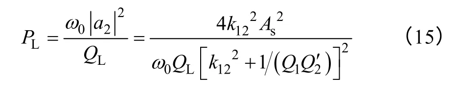
So when resonance occurs,active power on the load is a multivariate function of excitation power,resonance frequency,coupling coefficient and quality factor.Fig.4 shows the variation of normalized active power with load quality factor and coupling coefficient,wherein coupling coefficient axes uses logarithmic coordinates to facilitate observation.When operating frequency is kept constant,PLis not always increasing with the increase of k,but reaches maximum under a certain condition.In general,coupling coefficient changes with the spacing change,the other parameters are fixed values.Thus obtained condition of load active power reaches maximum is,and the maximum power is PLMAX=correspondingly.
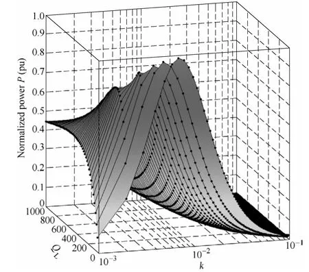
Fig.4 Normalized active power P as a function of k and QL
3.3 Analysis of EM coupling resonance transmission efficiency
As to system in Fig.5,EM power transfer to a2by a1through EM coupling resonance while the load obtains power by induction.To simplify problem,we assumed that external objects do not participate in energy exchange,and ignores load coil resistance RD.Active power consumption comes from load electric power,a1,a2power consumption themselves.While power consumption can be divided into the Joule losses and radiation losses of a certain dose,both can be embodied by equivalent quality factor.So overall efficiency η can be expressed as:
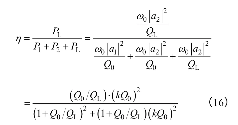

Fig.5 Transmission efficiency η as a function of Q0/QLand kQ0
And the maximum transmission efficiency and its prerequisites can be obtained from Eq.16 as:
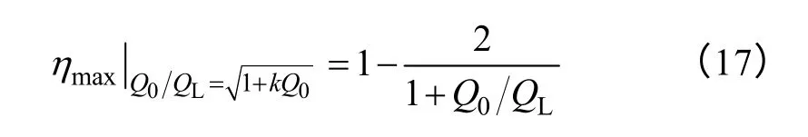
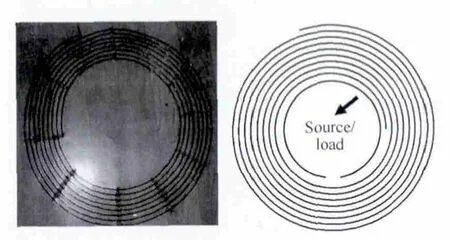
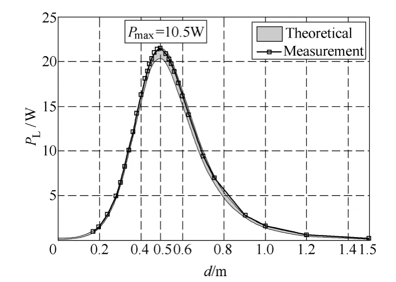
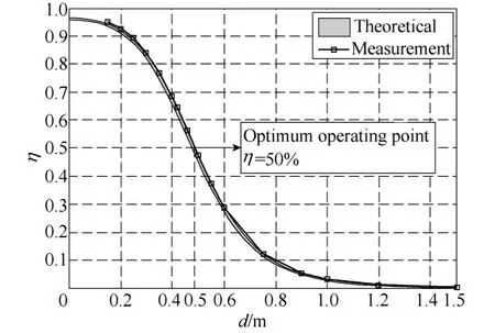
It can be drawn that linear EM resonant coupling system transmission efficiency depends mainly on two factors.The first item Q0/QLshows the role of impedance matching circuit.Here the load quality factor is generally less than the oscillator quality factor which ensures that transmission efficiency is always greater than zero.When QL< In order to verify the accuracy,a resonantly coupling system contains disc oscillators is designed.Moreover,the physical diagram and structure of disc oscillators,which have the same structure and resonant frequency,are shown in Fig.6 where the single coil indicates the source or device coil.The device coil is connected to a 220V/15W bulb from which the active power can be directly displayed by the luminance.Resonance occurs when system operates at 9.33MHz.When changing the spacing distance while keeping frequency constant,the active power load received is measured and relationship of them is shown in Fig.8.Dark region in figure indicates the theoretical results.There is an observation error about ±2.5% in measurement of quality factor leads to a certain value area.As spacing distance increases,the load power has experienced a process of first increased and then decreased,and reached the maximum power of 10.5W when spacing 0.5m,which verified Eq.15 and is consistent with theoretical calculation value. Fig.6 Physical diagram and structure of disc oscillator If system operates at natural resonant frequency,the maximum transmission efficiency curve can be measured as a function of different spacing,as shown in Fig.9.The observation error of Q also brings problems that the calculated results is a value area.The curve shows that,the two resonators closer,the higher the efficiency is.Transmission efficiency continues to decrease with distance increasing.It should be noted that,the receiving end does not obtain the maximum power at higher efficiency.Alternatives must be required by specific application of the load maximum power and optimal efficiency.Efficiency is 50% when spacing is 0.5m which matches the maximum power point in Fig.8.The operating distance is increased under the premise of maintaining high efficiency as much as possible.Therefore it is called optimal operating point,as shown in Fig.7. Fig.7 Experimental validation of optimum operating point Fig.8 PLas a function of distance between coils Fig.9 Transmission efficiency as a function of distance between coils Precondition of energy exchange in strong coupling can be expressed as:two resonators’ angular frequency equal,and the product of coupling coefficient and quality factor is far larger than 1,when system is symmetrical.Once meet this condition,theoretical maximum transmission distance can be approximately determined by curve in Fig.1c.The maximum active power that load achieves is closely related with quality factor and operating frequency.And power transmission capability is a function of k,Q and f which also indicates the load can only obtain maximum power in a certain position when circuit structure is determined.We further derived the expression of transmission efficiency which are constrained by two factors Q0/QLand kQ0.They indicate the contribution to efficiency by electrical structure and spacing distance between oscillators respectively.In order to verify the correctness of the theory,a 220V/15W bulb is used as load,and resonant coupling system with symmetrical disc coils are designed.Changing spacing and measuring relevant parameters,we get the function curve which varies with the load active power and transmission efficiency.The measurement results showed that,although there are some uncertainties in determining quality factor,the measured value has been within the error limits of±2.5% of theoretical calculation which demonstrates the accuracy of theoretical analysis. Reference [1]楊慶新,陳海燕,徐桂芝,等.無接觸電能傳輸技術(shù)的研究進展[J].電工技術(shù)學報,2010,25(7):6-13.Yang Qingxin,Chen Haiyan,Xu Guizhi,et al.Research progress in contactless power transmission technology[J].Transactions of China Electrotechnical Society,2010,25(7):6-13. [2]孫躍,夏晨陽,戴欣,等.感應(yīng)耦合電能傳輸系統(tǒng)互感耦合參數(shù)的分析與優(yōu)化[J].中國電機工程學報.2010,30(33):44-50.Sun Yue,Xia Chenyang,Dai Xin,et al.Analysis and optimization of mutual inductance for inductively coupled power transfer system[J].Proceedings of the CSEE,2010,30(33):44-50. [3]Elliott G,Raabe S,Covic G A,et al.Multiphase pickups for large lateral tolerance contactless powertransfer systems[J].IEEE Transactions on Industrial Electronics,2010,57(5):1590-1598. [4]張獻,楊慶新,陳海燕,等.電磁耦合諧振式無線電能傳輸系統(tǒng)的建模、設(shè)計與實驗驗證[J].中國電機工程學報,2012,32(21):153-158.Zhang Xian,Yang Qingxin,Chen Haiyan,et al.Modeling design and experimental verification of contactless power transmissin system via EM resonantly coupling[J].Proceedings of the CSEE,2012,32(21):153-158. [5]武瑛,嚴陸光,徐善綱.新型無接觸電能傳輸系統(tǒng)的穩(wěn)定性分析[J].中國電機工程學報,2004,24(5):63-66.Wu Ying,Yan Luguang,Xu Shangan.Stability analysis of the new contactless power delivery system[J].Proceedings of the CSEE,2004,24(5):63-66. [6]Kurschner D,Rathge C.Integrated contactless power transmission systems with high positioning flexibility[C].Power Electronics and Motion Control Conference,2008:1696-1703. [7]Louisell W H.Coupled mode and parametric electronics[M].New York:John Wiley &Sons Inc,1960. [8]Rafif E Hamam,Aristeidis Karalis.Coupled-mode theory for general free-space resonant scattering of waves[J].Physical Review,2007,75(5):1-5. [9]Haus H A.Waves and fields in optoelectronics[M].NewJersey:Prentice-Hall,1984. [10]Aristeidis Karalis,Joannopoulos J D,Marin Soljacic.Efficient wireless non-radiative mid-range energy transfer[J].Annals of Phisics,2008,3(23):34-48. [11]Stratton J A.Electromagnetic theory[M].New York:McGraw-Hill,1941. [12]Finkenzeller K.RFID-Handbook[M].2nd ed.Wiley,Hoboken,NJ,2003.4 Experimental study of EM coupling resonance

5 Conclusion
猜你喜歡
奧秘(創(chuàng)新大賽)(2020年1期)2020-05-22 02:42:38
小學科學(學生版)(2019年10期)2019-11-16 08:55:02
小哥白尼(趣味科學)(2019年12期)2019-06-15 10:56:32
人大建設(shè)(2018年2期)2018-04-18 12:17:00
校園英語·下旬(2016年12期)2017-03-31 08:58:28
特別文摘(2016年8期)2016-05-04 05:47:51
特別文摘(2016年8期)2016-05-04 05:47:50
電機與控制應(yīng)用(2015年10期)2015-03-01 03:50:45
電力工程技術(shù)(2014年6期)2014-03-20 14:19:46
電力工程技術(shù)(2013年6期)2013-03-11 16:51:16
- 電工技術(shù)學報的其它文章
- 工頻交流電暈放電下SF6氣體分解物形成的影響因素