
Analysis of magnetic field characteristics for different winding cylinder materials of a new type of magnetorheo-logical damper*
2014-07-31 20:22:02GuoliangHUWeiZHOUYiRUMingLONG
機床與液壓 2014年2期
Guo-liang HU , Wei ZHOU, Yi RU, Ming LONG
1School of Mechatronics Engineering, East China Jiaotong University, Nanchang 330013, China;2The State Key Laboratory of Fluid Power and Mechatronic Systems, Zhejiang University, Hangzhou 310027, China
Analysis of magnetic field characteristics for different winding cylinder materials of a new type of magnetorheo-logical damper*
Guo-liang HU?1,2, Wei ZHOU1, Yi RU1, Ming LONG1
1SchoolofMechatronicsEngineering,EastChinaJiaotongUniversity,Nanchang330013,China;2TheStateKeyLaboratoryofFluidPowerandMechatronicSystems,ZhejiangUniversity,Hangzhou310027,China
In order to avoid the magnetic flux leakage of winding cylinder of DSMRD, the magnetic field simulation models under different winding cylinder materials were built up to investigate the relationships between the magnetic flux leakage and three winding cylinders made by different kinds of materials. The simulation results show that winding cylinder made by No. 10 steel material has stronger ability to reduce flux leakage than the winding cylinder made by aluminum and stainless steel materials, and the winding cylinders made by aluminum and stainless steel materials have nearly same magnetic field intensity and induced voltage. The simulation results can provide some guidance to optimize magnetic field by finding a suitable winding cylinder material.
Differential self-induced magnetorheological damper (DSMRD), Winding cylinder, Magnetic field simulation
1.Introduction
MR damper is one type of semi-active control devices, which uses MR fluids to provide controllable damping forces. MR dampers have attractive advantages such as controllable damping force, broad operational temperature range, fast response, and little power consumption[1-2]. MR dampers have been widely used to mitigate vibration in vehicle suspension systems, buildings and bridges, and so on[3-6]. In order to make full use of the controllable damping characteristics of MRD, feedback control of the damping forces for MRD is necessary, which needs extra dynamic response sensor. However, it will increase the application cost and occupy the installation space. Furthermore, it will decrease the reliability. Therefore, a new type of MRD integrated magnetostrictive linear displacement transducer was developed by MTS Corporation[7]. Nehl et al. studied an integrated relative velocity sensor for traditional viscous damper[8]. In China, Chen invented a self-sensing magnetorheological damper with power generation[9]. Wang and his associates proposed an MR damper integrated with relative displacement sensor based on electromagnetic induction[10-11].
Aiming to solve the problems of large space for installation, high cost of maintenance and low system reliability caused by separation of magnetorheological damper and sensor which used in the semi-active control system, our group proposed a new type of differential self-induced magnetorheological damper (DSMRD) based on differential inducing theory[12-13]. In this paper, the relationship between the material of winding cylinder of DSMRD and working flux leakage was analyzed, which can provide some guidance for the optimization of DSMRD.
2.Structure and principle of DSMRD
Figure 1 shows the structure diagram of DSMRD. DSMRD is mainly composed of piston rod, piston head, winding cylinder, outer cover and floating head. When the excitation coil in the piston head is added direct current, the magnetic field would be generated at both ends of the piston head. The magnetic induction lines pass through the winding cylinder and along the outer cover to form a closed loop. The MR fluids in the annular gap would be magnetized, and it will generate high intensity shear force when the piston rod moves. Finally, the damping force is formed.
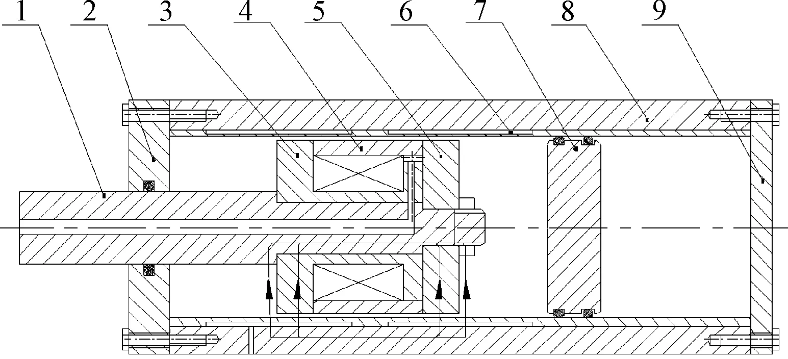
1.piston rod; 2.upper lid; 3.piston head; 4.coil ring; 5.coil board;6.winding cylinder; 7. floating piston; 8.outer cover; 9.lower lid
As the carrier of induced coil, winding cylinder is an important part of DSMRD. Figure 2 shows the structure of the winding cylinder which has two separate notches for differential winding coils. The coils will generate induced voltage when the piston head moves. Because of the differential winding, the export current is proportional to the subtraction of voltage in two coils.

Figure 2. Structure diagram of winding cylinder
3.Simulation analysis of different win- ding cylinder
The models of DSMRD were all the same except the winding cylinder materials. During the whole simulation, the difference of magnetic field and induced voltage were all depended on the materials of winding cylinder. Simulations were carried out under four situations, firstly is the none winding cylinder, namely normal MRD, secondly is stainless steel winding cylinder, thirdly is the aluminum winding cylinder, and the last is No.10 steel winding cylinder. The direct current was set 2A and vector potential was zero as boundary of DSMRD.
3.1.Static magnetic field analysis
Figure 3 shows the magnetic induction lines distribution. the model (a) was none winding cylinder, model (b) was the No.10 steel winding cylinder, model (c) was the Aluminum winding cylinder, and model (d) was stainless steel winding cylinder.
From the Figure 3, it can be seen that the model without winding cylinder had the lowest flux leakage and highest concentrated magnetic induction lines than the other three. The maximum of magnetic field intensity can reach 368 kA/m. The No.10 steel model had less flux leakage than Aluminum and stainless steel, the maximum magnetic field intensity was 327 kA/m. The magnetic induction lines transpired through the cylinder in two directions and primary flux area was obvious. The max magnetic field intensity of Aluminum model was 264 kA/m, and the max magnetic field intensity stainless steel model was 265 kA/m. Both (c) and (d) had more flux leakage and lower magnetic field intensity than the two others. The magnetic induction lines were not transpiring through but passing through the cylinder. Both primary flux areas were obvious.
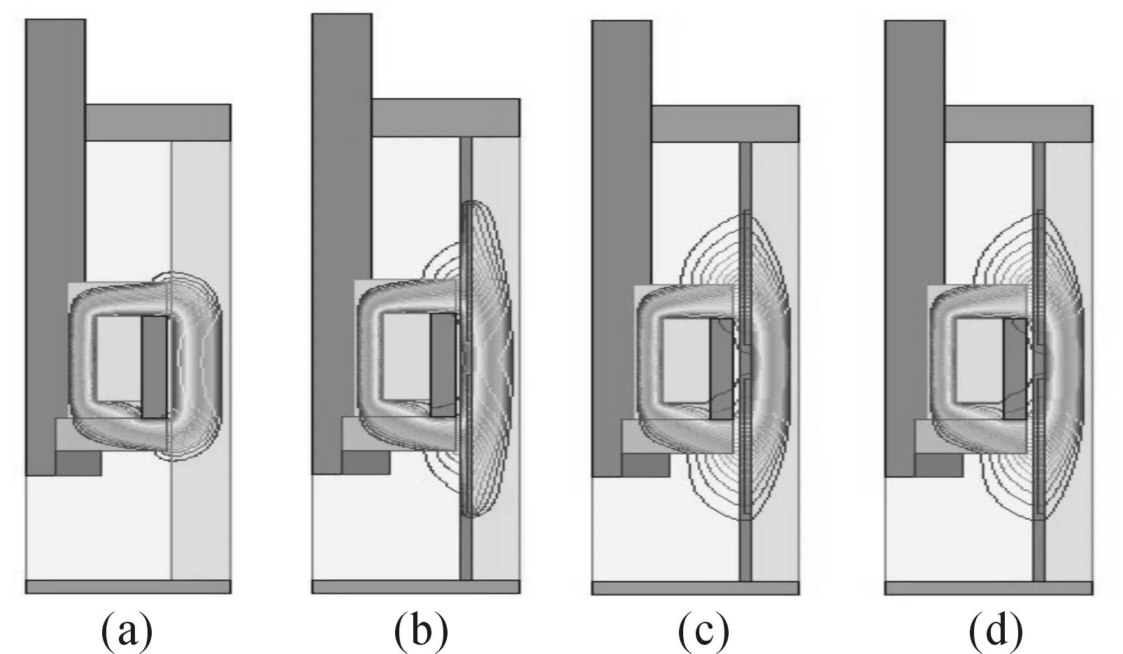
Figure 3. Magnetic induction lines distribution
Figure 4 shows the magnetic field intensity distribution under different winding cylinder situations. The magnetic field intensity of four models had the same trending; they are all falling from the left peak to the middle stable value, and then rising to the maximum amplitude at the right end. The intensity value of the one without winding cylinder reached the 368 kA/m. the intensity value of No.10 steel model reached 327 kA/m. The intensity values of Aluminum and stainless steel models reached 264 kA/m and 265 kA/m. The simulation results showed that the winding cylinder made by magnetic metal of No.10 steel had higher ability to generate magnetic field intensity and lower flux leakage than the one made by non-magnetic metal.
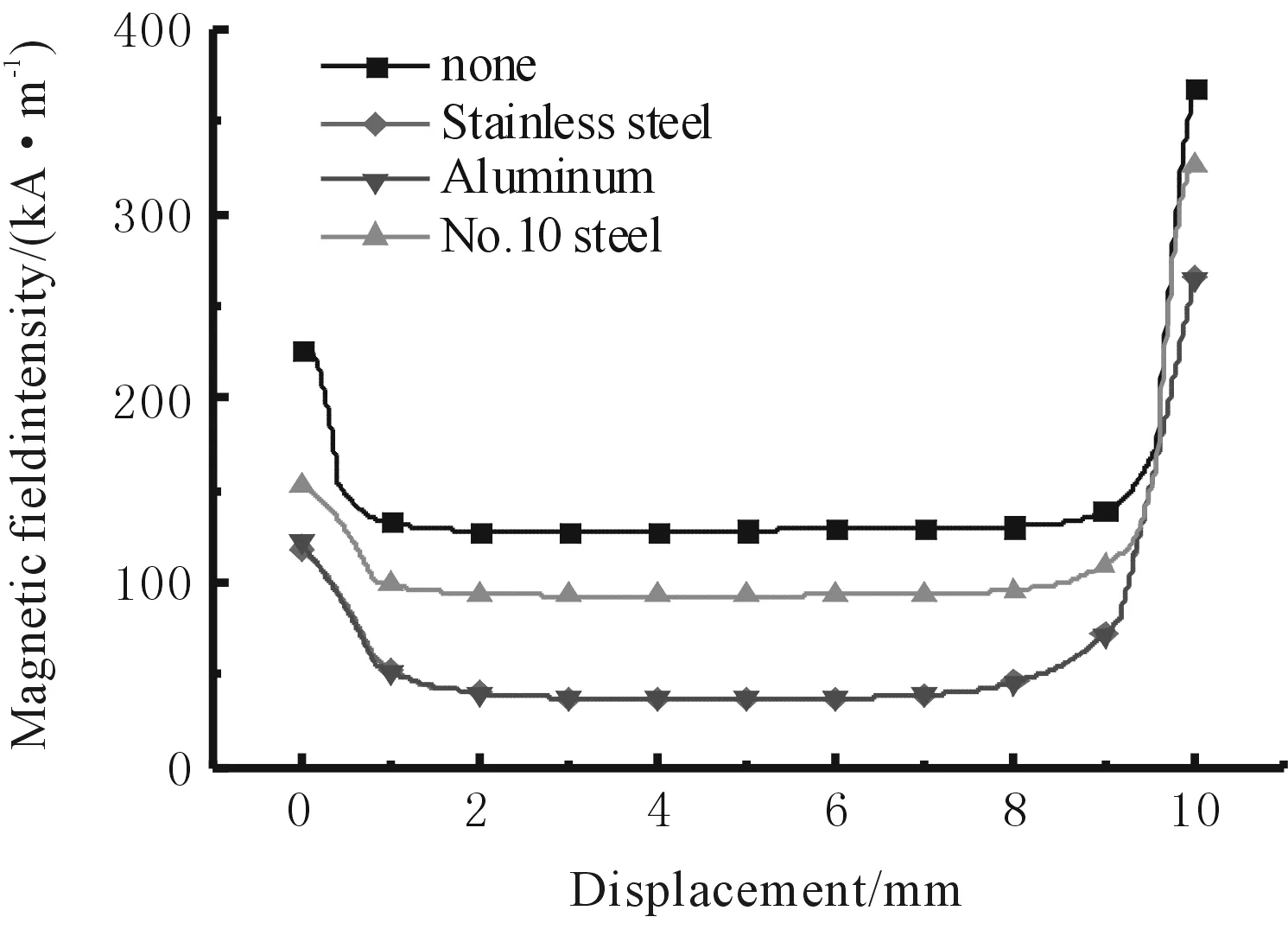
Figure 4. Magnetic field intensity distribution
3.2.Transient magnetic field analysis
As shown in Figure 2, the positive axisydirection was set along the piston head leaving out of the cylinder. During the simulation, the initial position of piston head was set at the distance that middle of two separate notches along the negative axisydirection 2 mm, and it was nominated as position 1. The distance that moving the piston head 1 mm along the positive axisydirection was set as position 2, and the distance that moving the piston head 1 mm along the position 2 direction was set as position 3. In order to investigate the relationship among winding cylinder under different materials and induced voltage, the dynamic models of winding cylinder materials of No.10 steel, Aluminum and stainless steel in three positions was built up. The sine AC electromotive force 14 V was input as excitation voltage. Figure 5 shows the induced voltage distributions under three winding cylinder materials. In order to observe easily, the curve of induced voltage of models in each position had been amplified 10 times.
Figure 5(a) showed that the winding cylinder of No. 10 steel material could generate induced voltage of max amplitude value 0.2 V during the piston head moving from position 1 to position 3. Figures 5(b) and 5(c) showed that models made by Aluminum and Stainless steel could also generate similar induced voltages whose max amplitude values were 0.171 V and 0.179 V respectively. The simulation results shows that winding cylinder of Aluminum and Stainless steel non-magnetic metals have little effect on amplitude and waveform of induced voltage.
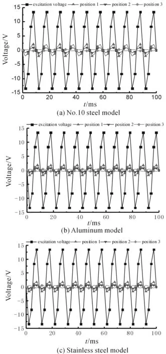
Figure 5. Induced voltage distributions under three winding cylinder materials
In order to observe the induced voltages that generated by the different models, the induced voltage values between the position 1 and position 2 was selected to compare, as shown in Figure 6. The winding cylinder made by No.10 steel magnetic metal had higher induced voltage than that of aluminum and stainless steel non-magnetic metals in the whole periods.
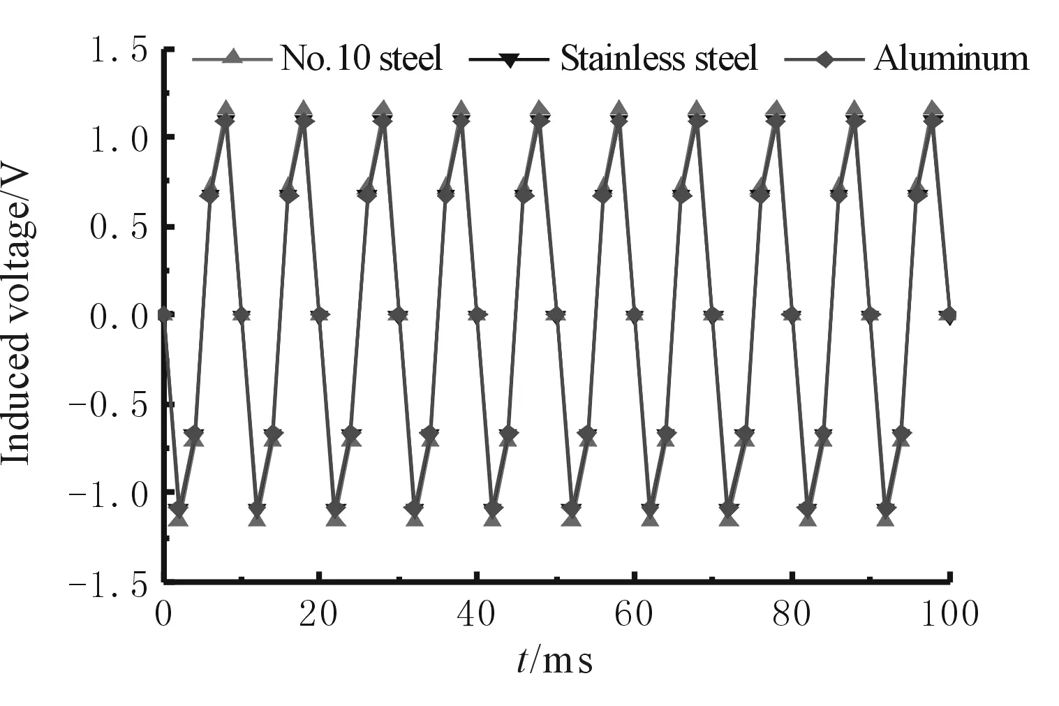
Figure 6. Induced voltage distribution of models
4.Conclusion
The simulation of magnetic field characteristics for winding cylinder shows that:
1) The winding cylinder made by magnetic metal No.10 steel has lower flux leakage than non-magnetic metals such as Aluminum and Stainless steel. The maximum of magnetic field intensity of No.10 steel cylinder is 327 kA/m.
2) All the winding cylinders made by magnetic metal or non-magnetic metal have the ability to generate induced voltage.
3) The cylinder made by magnetic metal has higher induced voltage than non-magnetic metal. The value of induced voltage generated by No.10 steel model is 0.2 V. However, the induced voltages generated by aluminum and stainless steel are 0.171 V and 0.179 V, respectively.
[1] Kamath G M, Wereley N M, Jolly M R.Analysis and testing of a model-scale Magnetorheological fluid helicopter lag mode damper[J].Journal of American Helicopter Society, 1996(44): 234-248.
[2] Yang G, Spencer B F, Carlson J D, et al.Large-scale MR fluid dampers: modeling, and dynamic performance considerations[J].Engineering Structures, 2002, 24(3): 309-323.
[3] Duan Y F, Ni Y Q, Ko J M.Cable Vibration control using magnetorheological dampers[J].Journal of Intelligent Material Systems and Structures 2006, 17(4): 321-325.
[4] Duan S W, Ni Y F, Chen Y Q, et al.Development of magnetorheological dampers with embedded piezoelectric force sensors for structural vibration control[J].Journal of Intelligent Material Systems and Structures.2008, 19(11): 1327-1338.
[5] Hiemenz G J,Choi Y T,Wereley N M.Seismic control of civil structures utilizing semi-active MR braces[J].Computer-Aided Civil and Infrastructure Engineering, 2003,18(1): 31-34.
[6] Lau Y K, Liao W H.Design and analysis of magnetorheologica dampers for train suspension[J].Proceedings of the Institution of Mechanical Engineers, Part F: Journal of Rail and Rapid Transit, 2005, 219(4): 261-276.
[7] David S N, Stephen W S, Arnold F S, et al.Magnetostrictive linear displacement transducer for a shock absorber[P].US 5952823, Patented Sep.14, 1999.
[8] Nehl T W, Betts J A, Mihalko L S.An integrated relative velocity sensor for real-time damping applications[J].IEEE Transactions on Industry Applications.1996, 32(4): 873-881.
[9] Chen C, Liao W H.A self-sensing magnetorheological damper with power generation[J].Smart Materials and Structures,2012, 21(2): 14-27.
[10]Wang D H, Wang T.Principle, design and modeling of an integrated relative displacement self-sensing magnetorheological damper based on electromagnetic induction[J].Smart Materials and Structures,2009,18(9):1-20.
[11]Wang D H, Bai X X, Liao W H.An integrated relative displacement self-sensing magnetorheological damper prototyping and testing[J].Smart Materials and Structures, 2010, 19(10): 1-19.
[12]Hu G L, Ru Y.Induction characteristics analysis of a new differential self-induced magnetorheological damper[J].Chinese Hydraulics & Pneumatics, 2012(10): 84-88.
[13]Hu G L, Ru Y, WANG H.Mechanical performance analysis for a new type of differential self-induced magnetorheological damper[J].Chinese Hydraulics & Pneumatics, 2013, 41(9): 6-9.
2013-12-08
10.3969/j.issn.1001-3881.2014.12.003
*Project supported by the Visiting Scholar Foundation of Key Laboratory of Fluid Power and Mechatronic Systems at the Zhejiang University(GZKF-201207), the Educational Commission and International Cooperation Project of Jiangxi Province of China (GJJ13341, 20132BDH80001), and the National Natural Science Foundation of China (51165005)
? Guo-liang HU, Professor. E-mail: glhu2006@163.com
- 機床與液壓的其它文章
- Influence of airflow uniformity over the duct outlet of vehicle air-condition on cooling performance*
- Design and realization of signal acquisition digital system for leak detection of water supply pipeline*
- Experimental study of chip formation and cutting force during
- Adaptive strategy of error anomaly processing in human simulated intelligent control*
- Phase-Lock technology of full digital UPS based on DSP*
- Software development for on-machine measurement of large CNC gear shape*