
Non-Gaussian approach: Withstanding loss and noise of multi-scattering underwater channel for continuous-variable quantum teleportation
2023-11-02 08:08:32HaoWu吳昊HangZhang張航YiwuZhu朱益武GaofengLuo羅高峰ZhiyueZuo左峙岳XinchaoRuan阮新朝andYingGuo郭迎
Chinese Physics B 2023年10期
Hao Wu(吳昊), Hang Zhang(張航), Yiwu Zhu(朱益武), Gaofeng Luo(羅高峰),Zhiyue Zuo(左峙岳),?, Xinchao Ruan(阮新朝),?, and Ying Guo(郭迎),2,§
1School of Automation,Central South University,Changsha 410083,China
2School of Computer Science,Beijing University of Posts and Telecommunications,Beijing 100876,China
Keywords: continuous-variable quantum teleportation, multi-scattering underwater channel, non-Gaussian operations
1.Introduction
Quantum teleportation facilitates the transfer of an unknown input state from Alice to Bob by leveraging quantum entanglement as the teleportation channel.[1,2]Continuousvariable quantum teleportation (CVQT) has garnered considerable attention due to its efficient source preparations and compatibility with existing devices.[3-6]Over time,the CVQT system has expanded from the initial fiber channel[7-9]to the free-space channel,[10-12]with experimental verification.[13-16]Nevertheless, achieving high-quality free-space quantum communication in underwater environments presents challenges due to the intricate composition of seawater and the dynamic fluctuations of external environmental factors.Light propagation in seawater entails a sophisticated process.Thus, a comprehensive understanding of the underwater optical channel’s characteristics and careful configuration of system parameters are pivotal for successful implementation of high-quality free-space quantum communication in underwater settings.
Mobley’s statements[17]propose a classification of seawater’s optical properties into two distinct categories: inherent optical properties (IOPs) and apparent optical properties(AOPs).IOPs primarily rely on optical parameters related to the transmission medium,such as absorption coefficient,scattering coefficient,attenuation coefficient,and volume scattering function.AOPs are not solely determined by the properties of the transmission medium, but they also take into account the geometric structure of the light field.Seawater exhibits three principal AOPs: radiance, irradiance, and reflectance.Previous research conducted by Prieuret al.[18]has made significant contributions to the optical classification of coastal and marine waters.Their work involved analyzing specific spectral absorption curves associated with phytoplankton pigments, dissolved organic matter, and other particulate matter.These studies have provided valuable insights into the definition and understanding of IOPs in different marine regions.
Recently, significant progress has been made in the theoretical analysis of underwater free-space quantum communication.Shiet al.[19]conducted a study utilizing Monte Carlo(MC) simulation and vector radiative transfer theory to examine the performance of underwater free-space quantum key distribution (QKD).Their findings demonstrated the feasibility of QKD in clear seawater.Similarly, Zuoet al.[20]investigated the evolution of quantum states over fading channels,considering factors such as absorption,scattering,turbulence,and ocean thermal noise of background light.These studies employed fixed IOPs or Beer’s law to simulate the attenuation effects of seawater, which simplifies the analysis and aligns reasonably well with experimental results.However, an important aspect that requires further attention in these investigations is the variation of absorption and scattering coefficients with depths within the same water body.[21]Additionally, Beer’s law, which assumes a perfect transmitter and receiver and considers all scattered photons are lost, may not fully capture the complexity of real-world scenarios.In practice, some scattered photons can still reach the receiver after multiple scattering events.[22]Consequently, the assumptions of Beer’s law lead to an underestimation of received light power, especially in scattering-dominated situations, such as turbid harbor water.
This paper presents an extension of prior research[23]by introducing a novel multi-scattering random channel model for underwater CVQT links.The proposed model employs MC simulation method and integrates the chlorophyll concentration model to effectively capture the spatialtemporal behavior of the channel.This study involves identifying key channel parameters and conducting an in-depth analysis of both light source sampling and receiver parameters within the proposed model.Based on this multi-scattering random channel model,the study investigates the influence of this channel on CVQT protocol.To further enhance the system performance in such a challenging channel, non-Gaussian (NG) operations are introduced to improve the overall system performance.
The paper is organized as follows.Section 2 provides a recapitulation of the schematic diagram of CVQT protocol and derives its fidelity using the characteristic function framework.In Section 3, a detailed description of the multiscattering stochastic channel model is presented, along with an analysis of the system’s excess noise.Section 4 introduces the proposal to utilize NG operations for improving the performance of CVQT.Finally,the paper concludes in Section 5,summarizing the key findings and contributions of the study.
2.CVQT protocol in seawater channel
Considering a CVQT-based quantum optical communication model as shown in Fig.1,and its implementation can be described as follows.
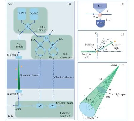
Fig.1.(a) The CVQT scheme.DOPA: degenerate optical parametric amplifier; LO: local oscillator; BS: beam splitter; ABS: asymmetrical beam splitter;AM:amplitude modulator;PM:phase modulator.(b)NG operations module diagram.ηNG:transmittance of NG operations beam splitter;n: input photon numbers;m: output photon numbers;PNRD:photon number resolving detector;PG:photon generator.(c)Geometry defining the simulation direction cosines.The green light vector illustrates the direction in the global coordinate frame before it encounters the next particle. e,the unit direction vector.(d)Beam attenuation transmission diagram.FOV:the field of view;Ab: photon absorption;BS:photon backscatter;FS:photon forward scatter;MS:photon multiple scatter.
Step 1 Alice prepares an optical two-mode squeezed vacuum state (known as an Einstein-Podolsky-Rosen (EPR)source)with a pair of degenerate optical parametric amplifiers,which can be represented by its covariance matrix
where A0and B0are two modes of EPR source,rrepresents the squeezing parameter.
Step 2 Alice sends mode B0to Bob through the seawater fading channel and leaves mode A0locally.The seawater link is characterized by transmittanceTsand excess noiseεs.Since mode A0remains local,it is assumed that the mode A0channel is an ideal one without loss and excess noise.Accordingly,the covariance matrixMA0B0becomes
where mode B1is the mode B0decayed by the fading channel,X,Y,andZare two-dimensional matrices given by
In our enhancement strategies, NG operations are performed on B0mode before passing through the lossy seawater channel,which will show in Section 4.
Step 4 Based on the measurement results,Bob performs coherent displacement operations using a phase modulator and an amplitude modulator.[9]The output stateρoutis obtained by asymmetric coupling of the modulated coherent beam and mode B1beam.Because of the participation of classical communication and the destruction of the input state by Bell measurement,this process is not superluminal communication and does not violate the no-cloning theorem.
In what follows,the fidelity of the CVQT protocol is calculated.Fidelity characterizes the proximity between the input state and the output state,given by
where the value ranges from 0 to 1.For coherent-state teleportation,fidelity can be simplified as[25]

Therefore the fidelity can be derived as
From Eq.(6),we can see that the fidelity of CVQT is mainly affected by transmittanceTs, excess noiseεs, and squeezing parameterr.Consequently,the accurate identification of channel parameters is the basis of CVQT performance analysis.
3.Multi-scattering random channel model
In this section, we introduce the seawater chlorophyll concentration model-based MC simulations algorithm,demonstrate the characteristics of the multi-scattering random channel,and analyze the excess noise of underwater links.
3.1.Monte Carlo simulations algorithm
The power attenuation of light in seawater is mainly affected by absorption,scattering,and turbulence.In most practical situations,compared with the strong absorption and scattering of seawater channel,the channel fading caused by turbulence can be ignored.[26]We will focus mainly on absorption and scattering.The specific model is given in Appendix A and Appendix B.
The average powerProf the optical signal received by the receiver in the underwater laser communication link can be simply summarized as
wherePtis the transmitted optical power,Wavis the average power weight reaching the receiver,Lis the link distance between the receiver and the light source,nrepresents the number of scattering times before reaching the receiver, the unit direction vectorseare shown in Fig.1, andδrepresents the random step size of each scattering.z·en >cos(FOV/2)andrepresent two conditions for a surviving photon to reach the receiver: the angle of incidence is less than half the receiver FOV and the projection of the photon scattering path in the propagation direction is equal toL.The statistical loss comes from the photon absorption and scattering(forward scattering and backward scattering)during propagation.However, the multi-scattering of some photons may lead to an increase in the received power, and the parameters of the receiver also affect the final received power.
On this basis, we employ MC simulations to rigorously characterize transmission attenuation in seawater.The idea of MC simulations is to establish a complex probability density function (PDF) based on known components.By randomly sampling these known processes,we can use these discrete samples to study channel characteristics under different types seawater,link distance,light source,and transceiver parameters.[27]The MC simulations steps can be described as follows.
Step 1 Setting the receiver parameters which include aperture size and FOV,and sampling the Gaussian spot to generate photons.
Step 2 The initial coordinates and propagation direction vector(νx,νy,νz)of photons are determined by randomly step sizeδ, polar angleθ, and azimuth angleφ, as shown in Fig.1.The initial propagation direction can be calculated asνx=sinθ0cosφ0,νy=sinθ0sinφ0,andνz=cosθ0.
Step 3 The current coordinates and power are iteratively calculated according to the initial coordinates and photon power.The new propagation direction of scattered photons can be expressed as
and equation (7) is used to determine whether the photon reaches the receiver.Note that the PDF of the above random variables change with the depth(the concentration of the corresponding substance), and each step requires a cumulative calculation of their corresponding depths to determine their extinction coefficients in the chlorophyll model.The specific algorithm and parameter settings are in Appendix C.
3.2.Monte Carlo simulation results
Using the MC simulation method introduced above, we can estimate the transmittance affected by seawater attenuation.The transmittance can be calculated as
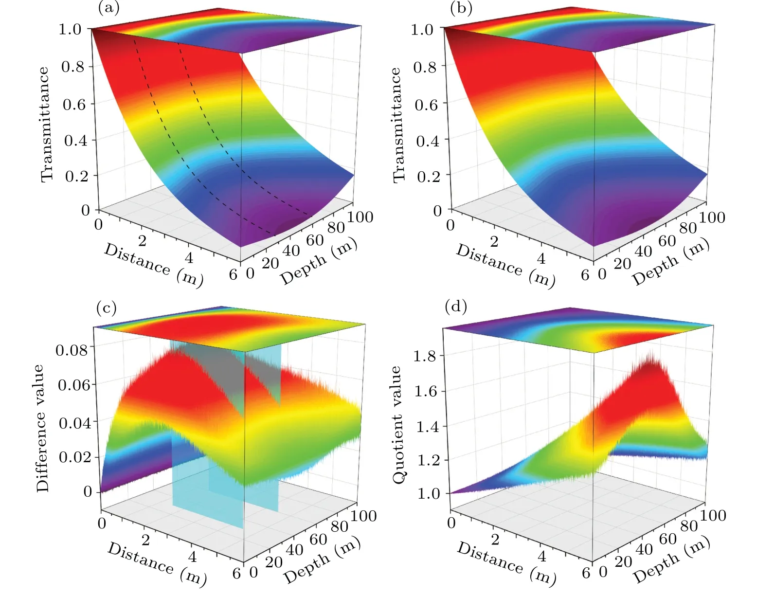
Fig.2.(a)Variation of transmittance TMC with depth d and transmission distance L based on MC simulation.(b)Variation of transmittance TBeer with depth d and transmission distance L based on Beer’s law.(c)The difference between TMC and TBeer.(d)The quotient between TMC and TBeer.
wherewiandwjrepresent the weight of emitted photons and successfully received photons,Neandnrrepresent the number of emitted photons and successfully received photons,respectively.According to the characteristics of the MC method,increasing the total number of photons in simulation can reduce the deviation of results, but increases the computational complexity, so we haveNe=106.As shown in Fig.2, all quantities vary with depth and transmission distance, and the magnitude of their values is indicated by the color.Figure 2(a)shows the simulation results of MC-based transmittance.It can be seen that the transmittance decreases exponentially with the increase of transmission distance.However, for the same transmission distance, there is a depth interval (30 m-60 m) where the transmittance is worse because the total attenuation is higher in this region.Compared with Fig.2(b),TMCandTBeerhave similar variations,butTMCis higher in the middle of the attenuation distance.As shown in Fig.2(c),TMCis more pronounced thanTBeerat medium attenuation transmission distances of 30 m-60 m in depth.This is due to the enrichment of scatterers(mainly NPA)in this interval, which emphasises the total power received from multi-scattered photons compared to Beer’s law,which assumes that all scattered photons are lost.From Fig.2(d), it can be seen thatTMCdecays more slowly thanTBeeras the link distance increases and is more clear at high scattering depths.
Take it a step further, we demonstrate the influence of Gaussian light source and receiver settings on simulation.As shown in Fig.1, we cut off the light spot (the beam propagates 6 m vertically downwards), and the simulation results are shown in Fig.3 (FOV as central axis, coordinates are±0.0127× aperture size).In contrast to Figs.3(a)-3(c), as the initial maximum divergence angle of the light source increases, the beam spot becomes larger and the light intensity becomes weaker.Compared with Figs.3(a), 3(d), and 3(g), as the beamwidth of the light source increases, the center of the spot becomes weaker because the larger beamwidth makes the initial position of the photon more dispersive.Figures 3(a), 3(e), 3(f) show that as the aperture size of the receiver increases, the received power increases accordingly.Figures 3(a), 3(h), 3(i) display that when the receiver FOV>30°,the received power is essentially unchanged.This may be because the photon without scattering or single-scattering enter the receiver at a small angle.
3.3.Excess noise analysis
Many noise sources interfere with underwater CVQT systems,including background noise,dark current noise,thermal noise, and shot noise.Generally, the original excess noise ?0with Gaussian-modulated states in the fiber system is about 0.01 in shot-noise units(SNU).[28,29]We take blackbody radiation and underwater ambient light as AOPs and analyze background noise.
Underwater ambient light whose primary source is the refracted sunlight and be absorbed in a certain depth.The solar background noise power is given by
whereA=πD2/4,Dis the aperture size(4 inches in our calculations),FOV=πis the field of view,Bfilter=0.01 nm andTfilter=1 are the narrow band filter spectral bandwidth and transmission,which value determined by the laser used to generate LO,[30]E=1440 W/m2is downwelling solar irradiance,R=1.25%is the reflectance,Lfacis direction factor(Lfac=1 vertical,Lfac=2.9 horizontal),[21]cavis the average extinction coefficient and calculate as
The blackbody radiation noise power is
Above all,the total excess noise can be expressed as
whereτ=1 ns is the effective sampling period,vis the frequency of the noise photons.Figure 4 shows the variation of total excess noise with depth in different propagation directions,it can be found that the excess noise of CVQT link horizontal transmission is much larger than that of vertical propagation.Moreover,the background excess noise of both propagation directions is reduced to less than 10-4for depths above 17 m.
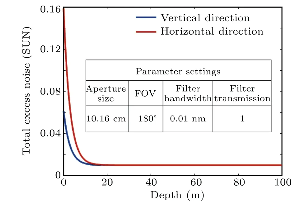
Fig.4.Attenuation curve of total excess noise with depth.
4.Performance analysis
The establishment of a quantum channel depends on the successful distribution of entangled pairs.However, the entangled states will degrade due to the influence of environmental attenuation,thus reducing the fidelity.Fortunately,we can make up for the environmental impact by using entanglement enhancement strategies, such as photon catalysis, photon addition,and photon subtraction,which are NG operations and have been used to improve the performance of quantum communication.[7,32,33]
These NG operations can be realized by ABS with tunable transmittanceηNGand conditional measurement, as shown in Fig.1(b).When the ABS inputs the signal state(B0mode), the auxiliary fock state|n〉 is injected from another port.After that,a perfect photon number projective measurement is performed and the PNRD is used to detect the output fock state|m〉.[32]Ifm <n, the photon number is added to signal states, which is called photon addition.On the contrary, ifm >n, the photon number is subtracted from signal states, which is called photon subtraction.Whenm=n, we call it photon catalysis.Here we consider zero-photon catalysis (m=n=0), single-photon addition (m=0,n=1) and single-photon subtraction(m=1,n=0)for simulation.
These NG operations are non-deterministic.[33]Therefore,the probability of success is an important index to study entanglement-based NG operations.For zero-photon catalysis, single-photon addition, and single-photon subtraction,their success probability is calculated as

Fig.5.The successful probability as a function of the transmittance ηNG of the ABS and squeezing parameter r.PC:success probability of zerophoton catalysis;PA:success probability of single-photon addition;PS:success probability of single-photon subtraction.
The success probabilityversusABS transmittanceηNGand squeezing parameterris shown in Fig.5.For zerophoton catalysis,it has the highest success probability,which increases with the increase ofηNGand decreases with the increase ofr.For single-photon addition, the success probability increases asηNGandrdecrease.For single-photon subtraction,the success probability is always smaller than singlephoton addition.Asrdecreases, the success probability increases first and then decreases.For smallerr, it gets the extreme points of the success probability at smallerηNG.
Next,we further demonstrate the effect of NG operations on underwater CVQT fidelity in terms of transmission distance and depth.Here, we comprehensively consider the success probability and setr=1.5,ηNG=0.3.For zero-photon catalysis,single-photon addition and single-photon subtraction,their fidelity is calculated as
The simulation results of fidelity are shown in Fig.6.The classic boundary of fidelity is 0.5.It is found that under the worst attenuation condition(depth at 44 m),the fidelity of the photon catalysis scheme propagates 4.9 m to reach the classical boundary, which is 3.2 m more than that of the original scheme (MC scheme,1.7 m).At a depth of 100 m, the background excess noise and attenuation are the minimum,the catalysis scheme propagating 8.8 m has more obvious advantages than the MC scheme propagating 3.1 m.Under the same conditions, the fidelity of the photon addition and subtraction schemes reaches the classical boundary after propagating 7.9 m and 1.8 m,respectively.
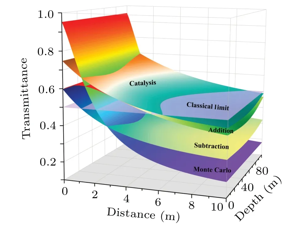
Fig.6.The fidelity as a function of transmission distance and depth.
Figure 7 shows the variation of fidelity with propagation distance for different NG operations.It can be seen that the NG operations have lower initial fidelity, however, as the propagation distance increases,the NG operations can reduce the fidelity decay rate.NG operations also improve the fidelity of the propagation process, which is more pronounced under high attenuation conditions.In summary, NG operations have different advantages in improving the fidelity of the CVQT system.Nevertheless, the NG operations are probabilistically successful, and higher performance may cause a lower probability of success.Fortunately,some scholars have proposed Gaussian post-selection methods to implement virtual NG operations.[34]which provides an opportunity for the practicality of NG operations.

Fig.7.Fidelity at different propagation distances.
5.Conclusion
We have investigated the NG approach-based CVQT protocol to overcome loss and noise in underwater links.The configuration of the protocol is displayed, and the fidelity in the characteristic function framework is derived.According to the optical transmitting properties of seawater,we proposed a multi-scattering random channel model, focusing on the algorithms and characteristics of this model.What is more,the excess noise of the CVQT links in different propagation directions is evaluated.Numerical simulations show that multiscattering random channels have higher transmittance under high scattering conditions,and for the same transmission distance,multi-scattering random channels have slower transmittance decay.Non-Gaussian operations can effectively improve transmission fidelity,as well as being able to slow down the fidelity decay rate under high attenuation conditions.
Appendix A:Settings of absorption parameters
Absorption is an irreversible loss of intensity, depending on the composition of seawater.[35]The light absorption effect in natural seawater is mainly caused by pure water, phytoplankton,chromophoric dissolved organic matter(CDOM),and nonalgal particle-mineral detritus (NAP).The total absorption characteristics of seawater are determined by the spectral absorption characteristics of these components and their concentrations.It can be subdivided as follows:[36]
The first term,apw(λL) is the wavelength-dependent absorption coefficient of pure seawater, and its values can be found in Ref.[18].
The second term,ac(λL)Cc(d)0.602represents the absorption coefficient of phytoplankton.ac(λL) is the spectral absorption coefficient of chlorophyll at a reference wavelength of 400 nm.Cc(d)is the variation function of chlorophyll(mainly chlorophyll-a) concentration with depth, which can be calculated as
The specific parameters setting are shown in Table A1.All the values are based on the data set S5 from Ref.[37].
The third term,afCf(d)exp(-kfλL) represents the absorption coefficient of fulvic acid,af=35.959 m2/mg is the spectral absorption coefficients of fulvic acid,Cf(d)is the concentrations of the fulvic acid andkf=0.0189 nm-1is the absorption slope coefficients of fulvic acid.
The fourth term,ahCh(d)exp(-khλL) represents the absorption coefficient of humic acid,ah=18.828 m2/mg is the spectral absorption coefficients of humic acid,Ch(d) is the concentrations of the humic acid andkh=0.01105 nm-1is the absorption slope coefficients of humic acid.Note thatCf(d)andCh(d)can be normalized byCc(d),and calculated as
The fifth term,adexp(-kdλL) represents the absorption coefficient of NAP,ad=9.721 m2/mg is the spectral absorption coefficients of NAP at a reference wavelength of 400 nm andkd=0.012 nm-1is the absorption slope coefficients of NAP.

Table A1.The settings of parameters.
Appendix B:Settings of absorption parameters
Scattering, on the other hand, refers to the deviation of light from the original path,which includes diffraction caused by particles with a size comparable to the wavelength or refraction caused by particles with a size much smaller than the wavelength.Similarly,for natural water bodies,the scattering of light by seawater is mainly caused by pure water and NAP,that is[38]
The first term,bpw(λL)is wavelength-dependent scattering coefficient of pure seawater.The second term,bs(λL)andCs(d) correspond to small particles scattering spectrum and concentration function.The third term,bl(λL)andCl(d)correspond to large particles scattering spectrum and concentration function.The specific parameters calculation are shown in Table B2.
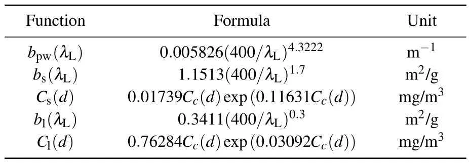
Table B2.The settings of each term.
The distributions of absorption and scattering coefficients are shown in Fig.B1, which both vary with the wavelength of incident light and the substance concentration at the corresponding depth.In the MC simulations,we chose the incident light wavelength of 532 nm, which falls within the seawater optical transmission window.[39]
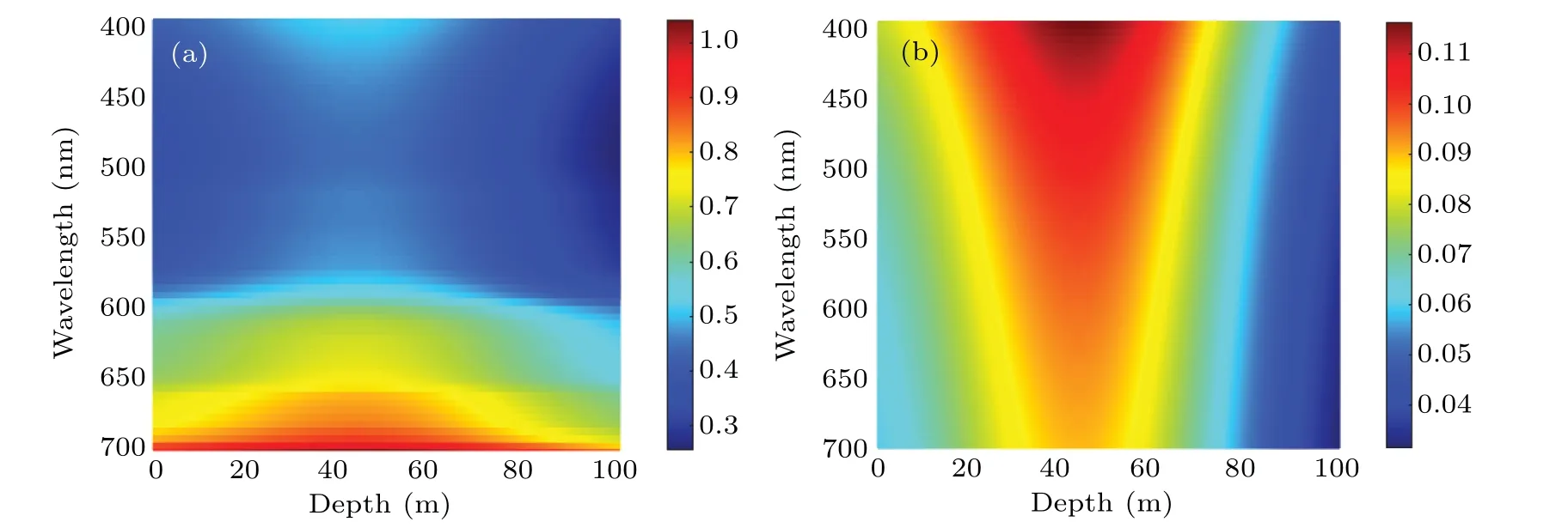
Fig.B1.(a)Variation of absorption coefficient a(λL,d)with depth d and wavelength λL.(b)Variation of scattering coefficient b(λL,d)with depth d and wavelength λL.Here, the value of the absorption and scattering coefficients are characterized by color, the unit of a(λL,d) and b(λL,d)are m-1.
Appendix C:Settings of MC simulations
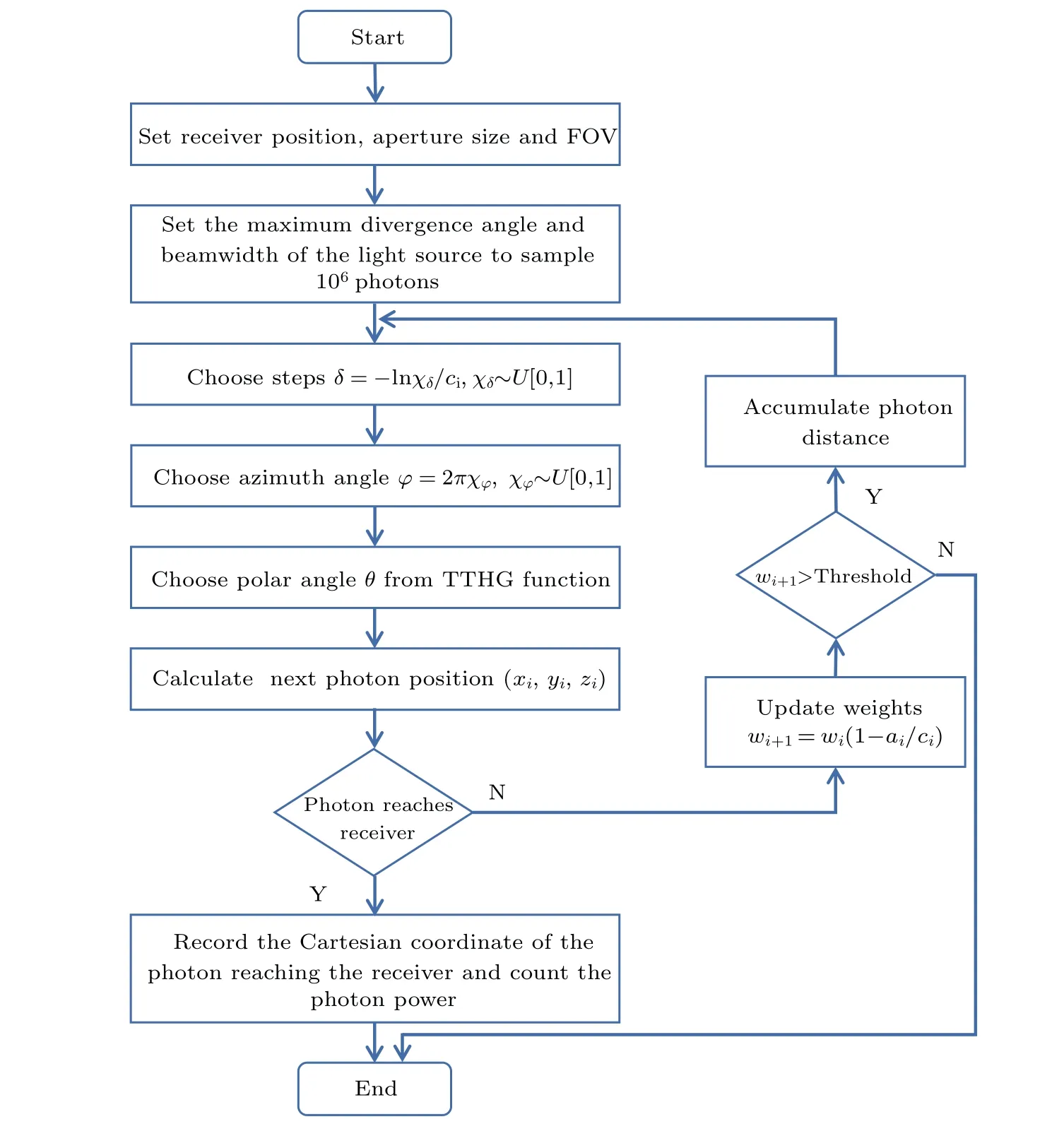
Fig.C1.Flowchart of MC simulation: a is absorption coefficients; b is scattering coefficients; c=a+b is total attenuation coefficients; U denotes uniform distribution;the two-term Henyey-Greenstein(TTHG)function is a common probability function of seawater scattering phase,which can be found in Ref.[40];the initial weight is 1;threshold is 10-4.

Fig.C2.The link geometry and photon trajectory for underwater CVQT system.
The selection of extinction coefficients for the model depends on the calculation of each depth, which is shown in Fig.C2.The transformations of the coordinate system and direction vectors after each scattering are given recursively by following equations:
Therefore, the depth of each step can be calculated asdi=δi(z·ei).
The pseudo code of the algorithm is shown in Algorithm 1.

Algorithm 1 MC simulations Input: Propagation distance L;receiver aperture size and FOV;light source maximum divergence angle and beamwidth.Output: Received photon location,number,power.1.Initialize δ,θ,φ randomly,W =1;2.Calculate initial direction vector and photon position;3.for W >10-4 do 4.if z·en >cos FOV 2 and ∑i=ni=0 δi(z ·ei)=L then 5.Reord photon location,number,power;6.else 7.Accumulate photon distance and depth;8.Search a,b,c corresponding to the depth in chlorophyll model;9.Randomly generate next δ,θ,φ,compute next current direction vector and photon position;10.end if 11.Update W;12.end for 13.return Simulation Over
Acknowledgements
Project supported by the National Natural Science Foundation of China (Grant No.61871407), the Natural Science Foundation of Hunan Province, China (Grant No.2021JJ30878), and the Key Research and Development Program of Hunan Province,China(Grant Nos.2020GK4063 and 2022GK2016).
猜你喜歡
今日農(nóng)業(yè)(2021年8期)2021-07-28 05:56:04
書香兩岸(2020年3期)2020-06-29 12:33:45
華人時(shí)刊(2019年21期)2019-05-21 03:30:38
藝術(shù)評(píng)論(2019年9期)2019-01-26 03:19:16
中華詩(shī)詞(2017年1期)2017-07-21 13:49:54
中國(guó)核電(2017年1期)2017-05-17 06:09:54
衛(wèi)星與網(wǎng)絡(luò)(2016年12期)2016-02-05 09:23:22
民間文學(xué)(2015年11期)2015-12-08 11:28:46
現(xiàn)代家長(zhǎng)(2014年5期)2014-07-18 22:34:44
英語學(xué)習(xí)(2012年1期)2012-04-29 00:44:03
- Chinese Physics B的其它文章
- Corrigendum to“Reactive oxygen species in plasma against E.coli cells survival rate”
- Dynamic decision and its complex dynamics analysis of low-carbon supply chain considering risk-aversion under carbon tax policy
- Fully relativistic many-body perturbation energies,transition properties,and lifetimes of lithium-like iron Fe XXIV
- Measurement of the relative neutron sensitivity curve of a LaBr3(Ce)scintillator based on the CSNS Back-n white neutron source
- Kinesin-microtubule interaction reveals the mechanism of kinesin-1 for discriminating the binding site on microtubule
- Multilevel optoelectronic hybrid memory based on N-doped Ge2Sb2Te5 film with low resistance drift and ultrafast speed