
Design of A Hot Redundant Communication Network for Drive Control Systems of Mobile Launch Platforms
2023-03-30 12:31:06LIDaopingZHUMaioxinLIChunlinCHENYaozuZHENGGuokun
Aerospace China 2023年3期
LI Daoping,ZHU Maioxin,LI Chunlin,CHEN Yaozu,ZHENG Guokun
Beijing Institute of Space Launch Technology,100076
Abstract: In order to ensure that a mobile launch platform is able to transport a launch vehicle which is assembled vertically on a complex orbit,a communication network for the drive control system was designed.Based on the characteristics of equipment of the drive control system and its position,Industrial Ethernet and Profibus were selected.To meet the requirements for reliability and maintainability of aerospace products,the communication network featured a hot redundant to avoid single point failure risk,so that if any point in the system fails,the control strategy of standby switches using heartbeat detection and parity check would ensure the normal communication and failure diagnostics,which could enable the transport mission of the launch vehicle to be completed smoothly.
Key words: mobile launch platform,drive control system,communication network,Industrial Ethernet,Profibus,hot redundancy
1 INTRODUCTION
As an important part of a mobile launch platform,a control system is used to control the motor to drive the platform for transporting a launch vehicle in vertical position smoothly and safely between the assembly plant and the launch location.The communication network links the devices and transfers the data amongst them.As the performance of the communication network affects the performance of the automatic control system directly,its design and layout play a very important role in transporting the launch vehicle.
With the development of computer technology,network communication technology and automatic control technology,fieldbus technology[1,2]has been widely used in industrial control systems.As the fieldbus system has the characteristics of high reliability,safety,interchangeability,openness,good dispersion,it has been widely adopted in the aerospace industry.Profibus[3,4]has passed rigorous certification standards,meets open protocols and standards,while Ethernet is one of the world’s most extensive networks and features like high speed,low cost and rich resources of hardware and software,Industrial Ethernet &Profibus communication networks are becoming the preferred communication networks for aerospace industrial products[5,6].
In this paper,a communication network for a mobile launch platform was designed.Taking into account the requirements for reliability,maintainability and safety of aerospace products,a suitable communication network system was designed according to the needs of a launch mission and appropriate hardware of the system.In order it to meet the mission requirements,the network also features a hot standby redundant communication structure to avoid single point failure risk.In case of failure of any device,the heartbeat detection and parity bit are set to switch the operation of the main and standby devices to ensure normal communication,fault detecting and decision triggers,which improve the reliability and maintainability of the system to ensure the successful completion of transportation of the vertically assembled launch vehicle.
2 DRIVE CONTROL SYSTEM
The drive control system is one of the most important subsystems of the mobile launch platform.It monitors the status of motors and controls them to drive the mobile launch platform to transport the launch vehicle between the assembly plant and the launch site.
The drive control system consists of a set of programmable logic controllers (PLCs),a host computer,16 inverters,a control panel,4 absolute encoders,several limit sensors and related control software.The host computer is based upon the Advantech IPPC series.A PLC has the features of hot standby redundancy,supports for multiple buses and protocols such as Industrial Ethernet,Profibus,PROFINET.The drive control system schematic diagram is shown in Figure 1.
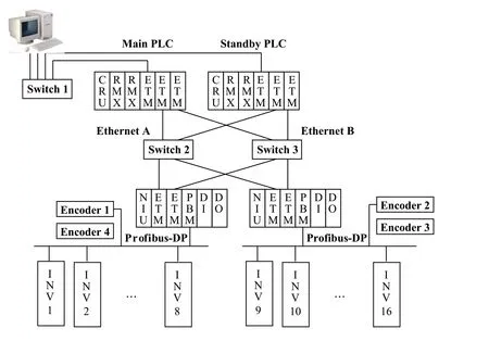
Figure 1 The drive control system schematic diagram
3 COMMUNICATION NETWORK STRUCTURE AND CONFIGURATION
The communication network is divided into two basic levels: basic automation level and process automation level.
3.1 Basic Automation Level
An industrial computer is selected for the main upper computer,the computer has two Ethernet cards for redundancy with two Ethernet cables to connect to the industrial Ethernet for data collection,monitoring and an installed Object linking and Embedding for Process Control (OPC) Server,which communicates with lower computer by using OPC communication protocols.The chip of a network interface controller (NIC)integrates multiple communication protocols such as OPC and others,and can improve the communication update cycles between the upper and lower computers and enhance the real-time capability of the system.
3.2 Process Automation Level
The PLCs are configured in two pairs of hot standby redundant structures composed of a master stations and two slave stations each.To complete the transportation task,the number of motors running at the same time is not less than 8,so the PLCs have two slave stations.Each slave controls 8 inverters which are on the same Profibus and acquires the values of two absolute encoders on each side of the platform.Each central processing unit (CPU) has two memory modules.Each memory module and the master memory on the other master station modules form a token ring network for data synchronization between the two CPUs.Two token ring networks are also redundant.
There are three Ethernet modules in each master station.Module 1 is used to communicate with upper computers and other equipment.Module 2 and 3 in two redundant different Ethernets are used to communicate with the slave stations.Each slave station has a network interface unit (NIU) module including two Ethernet modules in two redundant different Ethernets.The main station and slaves communicate with each other by using Ethernet Global Data (EGD) technology.
The transportation mission can be completed even with 8 failed motors.The PLCs have two slave stations,each slave controls 8 inverters and motors and the data collection of two encoders on both sides of the platform.Each station with a Profibus module as the master of Profibus,and each master connects 8 slaves of inverters and two encoders via a Profibus chain.The last encoder has installed a terminating resistor.Each inverter has installed a Profibus board for communication with master Profibus stations.
4 SOFTWARE DESIGN OF COMMUNICATION NETWORK
The software design takes full account of the reliability and maintainability.The parity bits are set in the network and used in the control system,which improve the system reliability and maintainability effectively.
4.1 Heartbeat Detection Between Upper and Lower Computers
A heartbeat detection of the parity bit between the upper and lower computers is applied.If parity bit errors occur within a certain time,it is regarded as an abnormal communication between the upper and lower computers,the system alarms will indicate the fault to the operators.
4.2 Parity Bits of PLC Stations
As EGD technology is used for communication between master and slave stations,the status of EGD can be used as the parity bit between master and slave stations of PLC.If a slave station is lost,the system alarms will warn the operators and those who can take the appropriate action.
4.3 Parity Bit of Profibus
The Profibus parity bit is an important parity bit in the system.It can realize the following functions:
1) The parity bit of each slave station of inverters is connected to another inverter whose motors are on the same axis,such as Inverter 1 and Inverter 8.If one slave station of inverters is lost,the other cannot work.
2) The Profibus parity bit of each slave connects to the output stop control word of the inverters whose motors are on the same axis.If one slave station of inverters is lost when the platform is moving,in order to ensure the smooth running of the platform and the balance of load,the output of the other inverter is also cut off.
3) The software of the PLC detects the parity bits of 16 inverters.If more than 8 slave stations are lost at the same time,to prevent additional hazards and damage to the equipment,the mobile platform is stopped.
4) Two encoders on different Profibus are on the same side of mobile platform for redundancy,one is main while the other is standby.If the parity bit indicates a failure of the main encoder,the software immediately starts the standby encoder and uses that data.When both two encoders fail,to ensure the completion of the task the software reverts to an emergency control mode and the mobile platform is controlled manually.
5 PERFORMANCE ANALYSIS OF COMMUNICATION NETWORKS
5.1 Real-time Analysis
The bus and protocols of the system and their update cycles are as shown in Table 1.It can be seen from the table that the system data update cycle is approximately 50 ms,so the real time of the system is perfect.
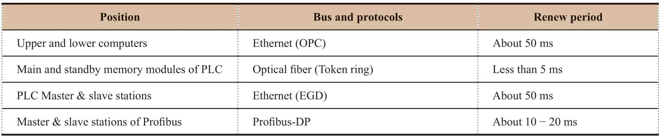
Table 1 Real-time analysis of the communication network
5.2 Reliability Analysis
According to the topology of the network,the reliability of the system is analyzed as shown in Table 2.
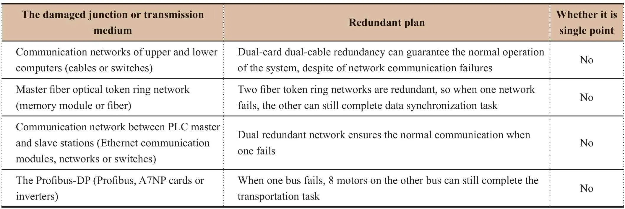
Table 2 Reliability analysis of the communication network
It can be seen from the above results that the reliability of the communication network is high.In addition to the Profibus,the hot standby redundancy enables the whole communication network operates without single point failure risk,which means that the failure of any part of the network will not affect the normal communication of the nodes.Although the slave stations of Profibus are potentially single points of failure,they are not a single point for the whole system because the system has two Profibus chains.If one Profibus fails,the other can still ensure the running of 8 motors to complete the task.
5.3 Maintainability Analysis
The faults of communication network and their diagnostic methods and solutions are shown in the Table 3.
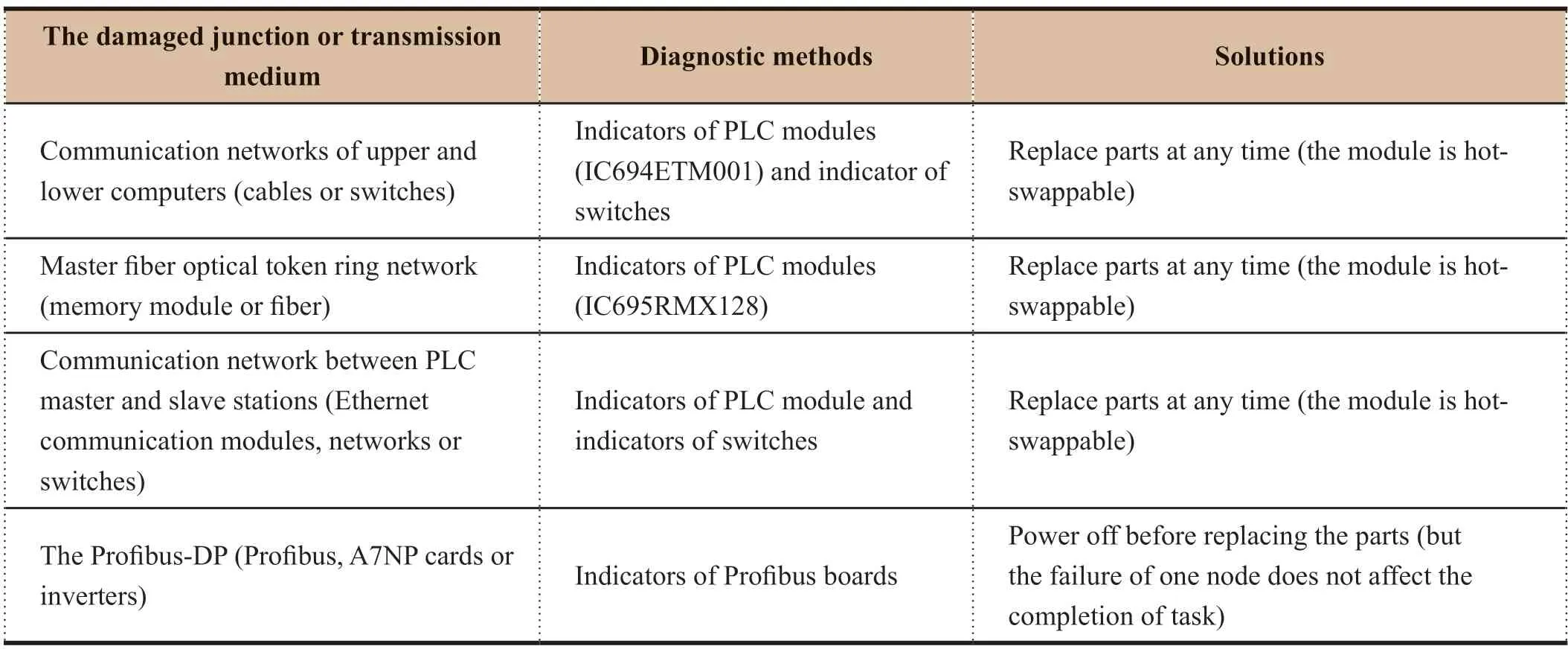
Table 3 Maintainability analysis of the communication network
It can be seen from the table that the maintainability of the network is strong.In addition to the Profibus node,the other nodes are hot-swappable and the faults of nodes on one single Profibus do not affect the completion of the task.
6 CONCLUSION
Taking into full account of the real-time performance,reliability,maintainability and safety and other factors,a communication network for the drive control system of the mobile launch platform was designed,which guarantees the functionality and performance that transportation of launch vehicles required,thus ensuring the completion of the transportation mission successfully.

- Aerospace China的其它文章
- Application of Artificial Intelligence in Outer Space Dispute Resolution
- Structural Analysis and Life Prediction of Thrust Chambers For Hydrogen-Oxygen Rocket Engines
- Dynamic Analysis of Launch Vehicle Piping Systems
- 12-Point Leveling Systems for Mobile Platforms and Emergency Plans
- Research on Frequency Improvement for LOX/kerosene Rocket Engine-Servo Loop
- Cooling Technology for Thrust Chamber of LM-5B LOX/kerosene Engine