
A band-pass frequency selective surface with polarization rotation
2023-03-13 09:18:52BaoQinLin林寶勤WenZhunHuang黃文準(zhǔn)JianXinGuo郭建新ZheLiu劉哲YanWenWang王衍文andHongJunYe葉紅軍
Chinese Physics B 2023年2期
Bao-Qin Lin(林寶勤), Wen-Zhun Huang(黃文準(zhǔn)), Jian-Xin Guo(郭建新),Zhe Liu(劉哲), Yan-Wen Wang(王衍文), and Hong-Jun Ye(葉紅軍)
School of Information Engineering,Xijing University,Xi’an 710123,China
Keywords: frequency selective surface(FSS),polarization rotation,band-pass
1.Introduction
Frequency selective surface (FSS) is a two-dimensional periodic structure,[1]which has been intensively studied for several decades.It is similar to metasurface although the concept of metasurface was proposed about a decade ago,and many different properties of electromagnetic(EM)waves can be tailored by various FSSs.A typical FSS can realize frequency selection, which has become a widely-used spatial filter.[1-10]In addition, a proper anisotropic or chiral FSSs can change the polarization state of EM wave, in recent years,a number of polarization converters have been proposed based on various anisotropic or chiral FSSs.[12-20]Furthermore, through reasonable design, some chiral FSSs can not only be used as spatial filters to realize frequency selection,but also as polarization converters to change the polarization state of EM wave, and this kind of FSS has been named as polarization-rotating FSS(PR-FSS).The first PR-FSS was proposed by Winkler,[21]it consisted of an array of substrate integrated waveguide (SIW) cavity resonators with two slots on the front and back surfaces, and the two slots were orthogonal to each other.So the polarization direction of all the transmitted wave in the pass band can be rotated by 90°;however, due to the highQ-factor of the SIW cavity resonators,the relative bandwidth of the first PR-FSS was only 4.6%.For PR-FSS is very useful in some applications, it has garnered much attention since the first one was proposed,and a number of different designs have been proposed in recent years.[22-27]However, the PR-FSSs proposed in Refs.[22-25] were still based on SIW technology,and the relative bandwidths of these PR-FSSs were all less than 8%.In Ref.[26], a V-shapedslot-based PR-FSS was proposed, although it was not based on SIW technology, its relative bandwidth was still only 8%.Recently, an aperture-coupled-patch PR-FSS was proposed in Ref.[27], and its relative bandwidth has been widened to 13.58%.
In this work, in order to further widen the bandwidth of PR-FSS, a novel PR-FSS is proposed based on an aperturecoupled-patch FSS.The unit cell of the PR-FSS is exactly antenna-filter-antenna(AFA)module,and the polarization directions of the upper and lower antennas in each AFA module are orthogonal to each other.Thus, through proper design,the PR-FSS can achieve frequency selection and 90 degrees polarization rotation simultaneously.In addition, its relative bandwidth is widened to 15.26%.
2.Design and analysis
Aperture-coupled-patch FSS is a widely used spatial band-pass filter.The unit cell structure of a common aperturecoupled-patch FSS is shown in Fig.1(a).It is composed of three patterned metal layers separated by two dielectric layers,in which the upper and lower metal layers are two identical square metal patches,and the middle one is a metal plate with a circular hole.In Ref.[28], this kind of FSS has been interpreted as an array of antenna-filter-antenna(AFA)modules,in which the two square metal patches have both been regarded as a microstrip patch antenna.This explanation means that the unit cell structure in Fig.1(a)can be equivalent to the one shown in Fig.1(b).However,the aperture-coupled-patch FSS can work under the incidence with arbitrary polarizations due to the symmetry of its unit cell structure, but the equivalent FSS composed of the unit cell in Fig.1(b)can only work under thex-polarized incidence because the coaxial feed probes of the two microstrip patch antennas in the unit cell structure are biased to one side along thexaxis for impedance matching,and the two microstrip patch antennas are bothx-polarized ones.In addition,in the unit cell structure in Fig.1(b),the circular hole on the middle metal layer adds a conductor via at the center as the coaxial feed port of the two microstrip patch antennas, its radius is reduced, thus the electromagnetic coupling between the upper and lower microstrip patch antennas is reduced, and the electromagnetic independence of the two microstrip patch antennas is enhanced.So the operation band of the equivalent FSS will move up a little.
The above description shows that the equivalent FSS is slightly different from the aperture-coupled-patch FSS.However, through detailed analysis, it is found that using the polarization sensitivity and enhanced electromagnetic independence of the two microstrip patch antennas in the unit cell structure of the equivalent FSS,we can make the polarization directions of the two microstrip patch antennas perpendicular to each other,and thus the equivalent FSS will work as a PRFSS.According to this idea, a PR-FSS is designed, and one of its unit cells is shown in Fig.1(c), in which the upper and lower microstrip patch antennas arex-andy-polarized antennas respectively.In addition, the width of the two microstrip patch antennas is reduced,and thus,the polarization sensitivity and electronic independence of the two microstrip patch antennas are further enhanced,which means that the operation band of the PR-FSS will continually move up a little, but the anticipated frequency selection and polarization rotation can be realized simultaneously by the PR-FSS.
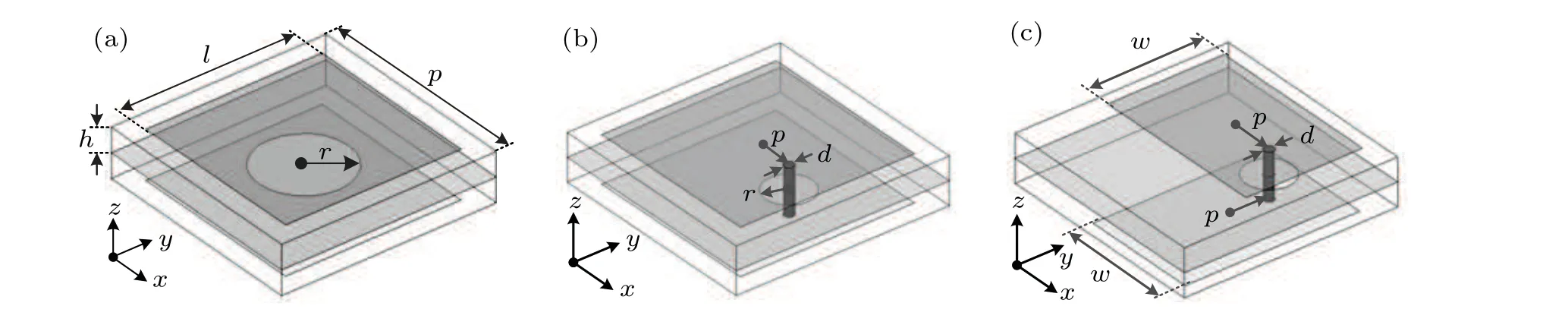
Fig.1.Unit cell structure of the aperture-coupled-patch FSS(a),equivalent FSS(b)and PR-FSS(c).
In order to verify the correctness of the above design,the designed PR-FSS, together with the aperture-coupled-patch FSS and the equivalent FSS,has been simulated by using Ansoft HFSS.Through the repeated simulations, the structural parameters of the unit cells in the three FSSs are determined.The structural parameters of the three unit cells are basically the same,the unit period isP=11.00 mm,and the two dielectric layers are both chosen as PTEF with a relative permittivity of 2.65 and a thickness ofh=1.20 mm; the side length of the two square metal patches isl=9.00 mm.However,in the PR-FSS’s unit cell,the two square metal patches are replaced by rectangular ones with a length ofl=9.00 mm and a width ofw=7.00 mm; in addition, the radius of the circular hole on the middle metal plate isr=2.8 mm in the unit cell of the aperture-coupled-patch FSS,but in the unit cell of the equivalent FSS and PR-FSS,the radius of the circular hole is reduced tor=1.20 mm.Furthermore,a conductor via with a diameter ofd=0.5 mm is added at the center of the circle hole,which,as the feed probe of the two microstrip patch antennas, deviate from the center of the two metal patches,and the deviation value in the unit cell of the equivalent FSS isp=2.6 mm,but that in the PR-FSS’s unit cell is reduced top=2.5 mm.
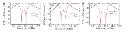
Fig.2.Simulated results of the aperture-coupled-patch FSS(a),equivalent FSS(b)and PR-FSS(c)under the x-polarized normal incidence.
The simulated results of the three FSSs under thexpolarized normal incidence, as shown in Fig.2, indicate that the three FSSs all have a good bandpass performance, but their operation frequency bands gradually move up.The frequency band of the aperture-coupled-patch FSS is between 7.04 GHz and 8.44 GHz, and that of the equivalent FSS is between 8.45 GHz and 9.56 GHz.For the final-designed PRFSS,the frequency band moves up to 8.84-10.30 GHz,in addition, the transmitted wave in the pass band is almost completely changed to ay-polarized one, the magnitude of the cross-polarized transmission coefficientsTxyis much close to 0.0 dB, and the minimum value in the pass band is still only-0.17 dB.It is indicated that these simulated results are fully consistent with the above theoretical prediction, and the PRFSS can realize anticipated frequency selection and polarization rotation in a wide frequency band with a relative bandwidth of 15.26%.In addition, through its operation band has moved up a little,its unit cell size is still only 0.35λ0,whereinλ0is the central wavelength of the FSS.Compared with the previous PR-FSSs proposed in Refs.[22-25],the unit cell size is much smaller, and the PR-FSS structure is still very compact, but the operation frequency band has been widened exponentially, which means the designed PR-FSS has excellent performance,and it is a very proper design.
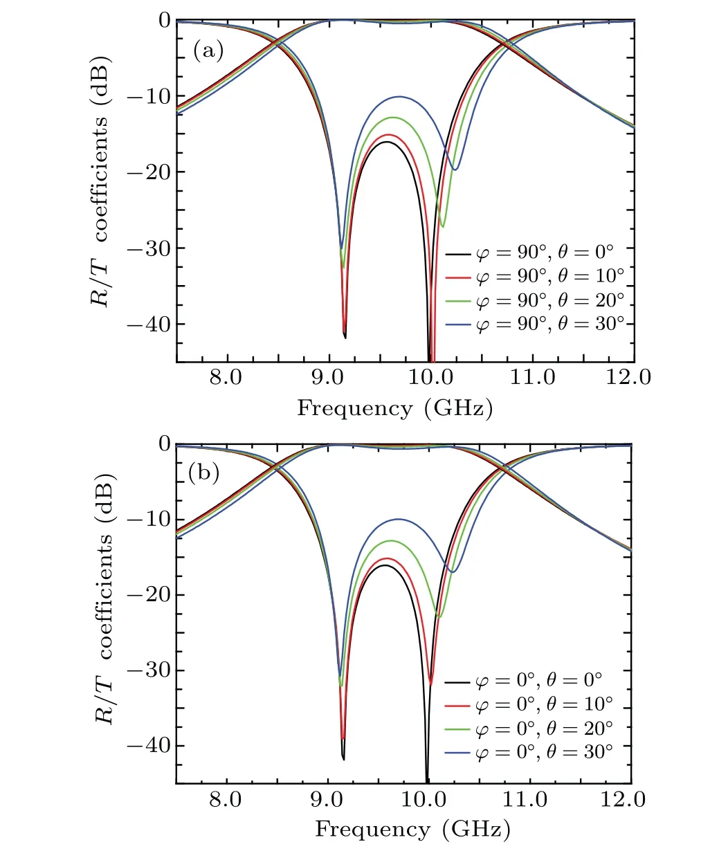
Fig.3.Simulated results of the PR-FSS under TE-(a)and TM-polarized(b)oblique incidences.
Furthermore, to analyze the angular stability of the design, the PR-FSS has been simulated under different oblique incidences.Because the upper microstrip patch antenna in the unit cell of the PR-FSS is ax-polarized one,in order to ensure that the incident wave can be accepted by it,the azimuth angleφof the TE-polarized incident wave is chosen as 90°,but that of the TM-polarized incident wave is changed to 0°.When the incident angleθis set to different values, the obtained simulated results are shown in Fig.3.In Fig.3(a),it is shown that when the incident angleθis increased to 30°, the magnitude of the co-polarized reflection coefficient under TE-polarized oblique incidence can still be kept lower than-10 dB in the whole pass band;in addition,Fig.3(b)indicates that the simulated results under the TM-polarized oblique incidence are almost the same as those under TE-polarized oblique incidence,which illustrates that the proposed PR-FSS has a certain angular stability under both TE and TM-polarized incidences.
3.Experimental validation
Finally, to experimentally verify the performance of the proposed PR-FSS, one laboratory sample was fabricated by using the standard print circuit board (PCB) technique,which consists of 25×25 unit cells with a total area of 275 mm×275 mm as shown in Fig.4(a).The PR-FSS sample has been measured by using free-space measurement techniques, and the measurement was carried out in a microwave anechoic chamber by using an Agilent E8363B network analyzer and two identical standard-gain horn antennas.The schematic of the transmission measurement setup is shown in Fig.4(b),in which the PR-FSS sample,together with the transmitting and receiving antennas, is just located on thez-axis,and the polarization of the transmitting and receiving antenna are in thex- andy-axis directions, respectively.In addition,for the co-polarized reflection measurement, the transmitting and receiving antennas are placed adjacently in the same direction.The laboratory samples have been measured under thex-polarized normal incidence and TE, TM-polarized oblique incidences with an incident angle of 30°.In the measurement under TE oblique incidence,the PR-FSS sample has been rotated by 30°around its vertical axis (i.e., thex-axis), and the receiving antennas has been rotated by 60°around thex-axis when measuring the co-polarized reflection.In addition,in the measurement under TM oblique incidences,the PR-FSS sample and two horn antennas have all been rotated by 90°around thez-axis at first,and then repeated the measurement process under TE oblique incidence.The measured results under thex-polarized normal incidence and TE, TM-polarized oblique incidences are shown in Figs.4(c)and 4(d),respectively,and it is shown that the PR-FSS can realize frequency selection and polarization rotation under all the incidences;in addition,except for a slight deviation caused by fabrication error and measurement tolerance,the measured results are in reasonable agreement with the simulated results.
Table 1 lists a comparison of the proposed PR-FSS with previous works proposed in Refs.[21-27],and it is shown that the PR-FSS has a significant advantage in the bandwidth expansion.Moreover,it has a better bandpass performance,and the insertion loss in its pass-band is only 0.17 dB,which illustrates that the proposed PR-FSS is more practical.
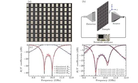
Fig.4.Photographs of the laboratory sample(a),the schematic of the measurement setup(b),and the measured results under normal incidence(c)and under oblique incidence with incident angle of 30° (d).
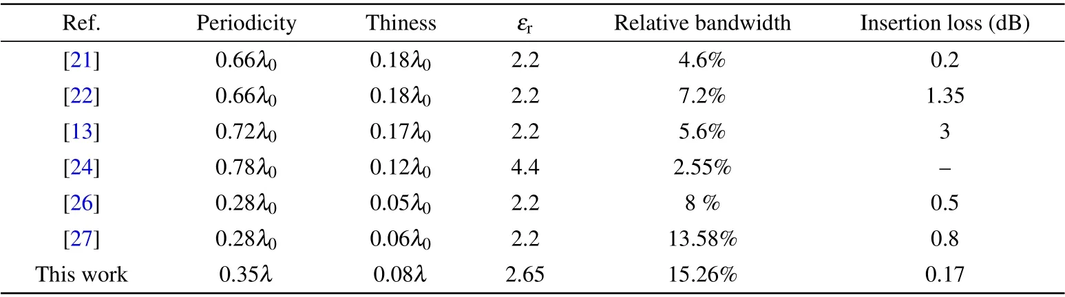
Table 1.Comparison of this work with previous works.
4.Conclusions
In this paper, a novel PR-FSS is proposed based on an aperture-coupled-patch FSS.Because the unit cell structure of the PR-FSS is an AFA module and the polarization directions of the upper and lower antennas in each unit cell are orthogonal to each other, the numerical simulations show that the PR-FSS can achieve frequency selection and polarization rotation simultaneously in the frequency band from 8.84 GHz to 10.30 GHz with a relative bandwidth of 15.26%.Finally,one effective experimental verification is carried out,and a reasonable agreement has been observed between the simulated and experimental results.
Acknowledgements
Project supported by the National Natural Science Foundation of China(Grant No.62072378)and Xi’an Science and Technology Plan Project,China(Grant No.GXYD20.4).

- Chinese Physics B的其它文章
- Analysis of cut vertex in the control of complex networks
- Atlas of dynamic spectra of fast radio burst FRB 20201124A
- Investigating the characteristic delay time in the leader-follower behavior in children single-file movement
- Micro-mechanism study of the effect of Cd-free buffer layers ZnXO(X =Mg/Sn)on the performance of flexible Cu2ZnSn(S,Se)4 solar cell
- Thermally enhanced photoluminescence and temperature sensing properties of Sc2W3O12:Eu3+phosphors
- Heterogeneous hydration patterns of G-quadruplex DNA