
Multiple modes of perpendicular magnetization switching scheme in single spin–orbit torque device
2022-10-26 09:54:42TongXiLiu劉桐汐ZhaoHaoWang王昭昊MinWang王旻ChaoWang王朝BiWu吳比WeiQiangLiu劉偉強andWeiShengZhao趙巍勝
Chinese Physics B 2022年10期
關(guān)鍵詞:王朝
Tong-Xi Liu(劉桐汐) Zhao-Hao Wang(王昭昊) Min Wang(王旻) Chao Wang(王朝)Bi Wu(吳比) Wei-Qiang Liu(劉偉強) and Wei-Sheng Zhao(趙巍勝)
1Fert Beijing Institute,MIIT Key Laboratory of Spintronics,School of Integrated Circuit Science and Engineering,Beihang University,Beijing 100191,China
2College of Integrated Circuits,Nanjing University of Aeronautics and Astronautics,Nanjing 211106,China
Keywords: spin–orbit torque(SOT),field-like torque,magnetization switching,perpendicular magnetization
1. Introduction
Magnetic random access memory (MRAM) has become a promising candidate for both embedded and standalone applications[1]due to its non-volatility, low power, high speed, and nearly unlimited endurance. The write technology of the MRAM, which is reflected by the mechanism of magnetization switching, has long been attracting numerous research interests as it significantly determines the performance of the MRAM. To date, MRAM written by spintransfer torque (STT) has made great progress of both academic research and industrial applications.Nevertheless,newgeneration MRAM has been explored by researchers to outperform the STT-MRAM.Typically, spin–orbit torque(SOT)MRAM shows great potential in non-volatile memory and inmemory computing.[2–5]Comparing with the STT-MRAM,the read and write paths are separated in the SOT-MRAM,resulting in higher reliability. Furthermore, the SOT-driven magnetization switching is as fast as several hundreds of picoseconds,[6,7]which qualifies the SOT-MRAM to be used in high-level caches.
Actually, the SOT-driven magnetization switching is achieved under the joint effects of multiple factors, such as magnetic anisotropy field, Gilbert damping torque, dampinglike torque, field-like torque,etc. Most notably, by changing the relative proportions of these factors,the behavior of magnetization switching varies dramatically. Overall,both unipolar and bipolar switching have been proposed with different SOT mechanisms.[8–14]As shown in Table 1, for the unipolar switching,the magnetization is switched into the opposite state once an SOT current larger than the threshold is applied,regardless of the current polarity. For the bipolar switching,the final magnetization state is dependent on the polarity of the applied SOT current. The combination of unipolar and bipolar switching could benefit the function extension of the SOT-based memories or circuits. However, up to now these two modes of magnetization switching are implemented with different devices separately, which degrades the design flexibility of the related memories or circuits.
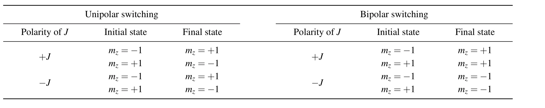
Table 1. Unipolar and bipolar switching behaviors. In this table,J is the applied SOT current density with a magnitude larger than the threshold. mz=-1 and mz=+1 represent the two states for storing binary data.
In this work,we propose a novel scheme that implements both unipolar and bipolar switching of the perpendicular magnetization within a single SOT device. The mode of switching is only dependent on the amplitude of the applied current. The change of switching mode is mainly attributed to the modulation of the field-like torque. Our proposal makes it possible to design the SOT-based memories or circuits with good reconfigurability.
2. Device model
In this study, the magnetization switching occurs in a common SOT magnetic tunnel junction (MTJ) with perpendicular anisotropy as illustrated in Fig.1. No special structure is required in this device. A charge current passing through the heavy metal induces the SOT which switches the perpendicular magnetization of the free layer(FL).Generally,an additional bias field is used to break the symmetry so that the switching process becomes deterministic.This bias field could be generated inside the device by using antiferromagnet[15–18]or magnetic hard mask.[19]The magnetization dynamics of the FL can be described by a modified Landau–Lifshitz–Gilbert(LLG)equation as follows:

Here,mandσare the unit vectors of the FL magnetization and SOT-induced spin polarization,respectively.Jis the SOT current density. The effective field includes the contribution of the magnetic anisotropy field,the demagnetization field and the external field.ξ=γˉh/(2etFMs)is a device-dependent parameter, withγbeing the gyromagnetic ratio, ˉhthe reduced Planck constant,ethe electron charge,tFthe free layer thickness,Msthe saturation magnetization. The default values of some magnetic parameters are configured as follows, unless otherwise stated. The damping constant (α) is 0.05. The effective anisotropy constant is 1.5×10⁵J/m3.tF= 1 nm,Ms=1×10⁶A/m,λDLandλFLrepresent the strength of the damping-like and field-like torques,respectively,λDLis equivalent to the spin Hall angle whose default value is 0.3. More details are described elsewhere.[11]
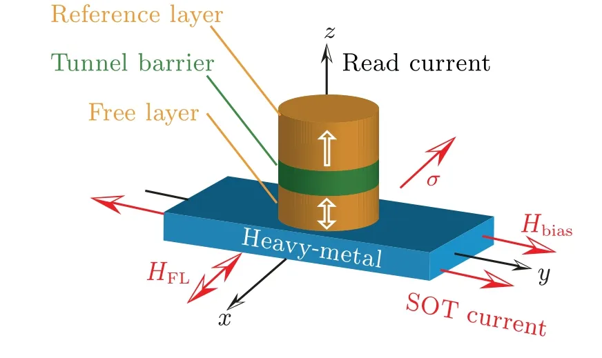
Fig.1. Device structure and coordinate system in this study.
3. Results and discussion
In our proposal, the field-like torque must be strong enough to implement multiple modes of switching within the above magnetic device. Strong field-like torque has been reported in previous researches.[20–22]Moreover, a number of researches have demonstrated that both the strength and sign ofλFL/λDLcan be adjusted by tuning the material types or fabrication processes.[20,23,24]The strength of field-like torque is related to multiple factors such as layer thickness, material system, interfacial intermixing,etc. This is a complicated issue and still under exploration. Recent researches have reported several methods of enhancing the field-like torque.[22,24]In this workλFL/λDL=4 is chosen for a preliminary study. Accordingly,macrospin simulation results under the various current densities are shown in Fig. 2. For all the cases, the device is subjected to a bias field of 20 mT,and the pulse width of SOT current is set to be 0.5 ns. Both unipolar and bipolar switchings can be clearly observed from the simulation results. First, no switching occurs when the current density is insufficient, since the torque is too weak to overcome the energy barrier. Second, unipolar switching is achieved if the current density is set to be an intermediate value(see Figs.2(b)and 2(e)). Finally,the switching process becomes bipolar while the current density is further increased(see Figs. 2(c) and 2(f)). Therefore, the mode of switching can be easily changed by adjusting the current density. The detailed mechanisms are analyzed below.
The large field-like torque plays a dominant role in the unipolar switching process. According to Eq. (1), the fieldlike torque is equivalently induced by an in-plane magnetic field (HFL). ForλFL/λDL=4 andJ=6×10¹¹A/m2, this equivalent magnetic field is aroundλFLξJ/γ ≈237 mT,which is much higher than the bias field (20 mT). In this case, the magnetization vector almost precesses around theHFLwith a speed ofγμ0|HFL|,[13]as shown in Figs.3(a)and 3(b). Thus,the magnetization vector will turn to the in-plane direction(i.e.mz=0) after a delay of aboutπ/(2γμ0|HFL|), which is in agreement with the results of Figs.2(b)and 2(e). Finally,the magnetization vector is stabilized at an equilibrium position under the action of various torques.
The bipolar switching occurs if a larger current density is applied. In this case, the field-like torque is enhanced so that the magnetization vector is driven closer to the axis ofσ.Then the torque induced by the bias field (Hbias) is nearly aligned to±σ×Hbias. Note thatσandHbiasare parallel toxaxis andyaxis,respectively(see Fig.1),thus this torque is almost oriented towards?zaxes. Depending on the direction of the applied current,the magnetization vector is switched to the+zaxis or-zaxis,as shown in Fig.3(c)or Fig.3(d). Overall,the joint effects of the bias field and huge field-like torque lead to the bipolar switching.
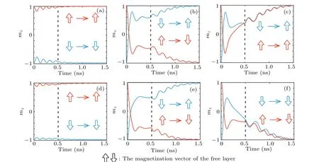
Fig. 2. Macrospin simulation results of z-component magnetization (mz), indicating that ((a), (d)) no switching occurs while J=2×10¹¹ A/m2,((b),(e))unipolar switching occurs while J=6×10¹¹ A/m2,((c),(f))bipolar switching occurs while J=7×10¹¹ A/m2,((a)–(c))current is applied along+y axis,and((d)–(f))current is applied along-y axis. The SOT pulse is withdrawn at 0.5 ns(as marked by the vertical dotted line).
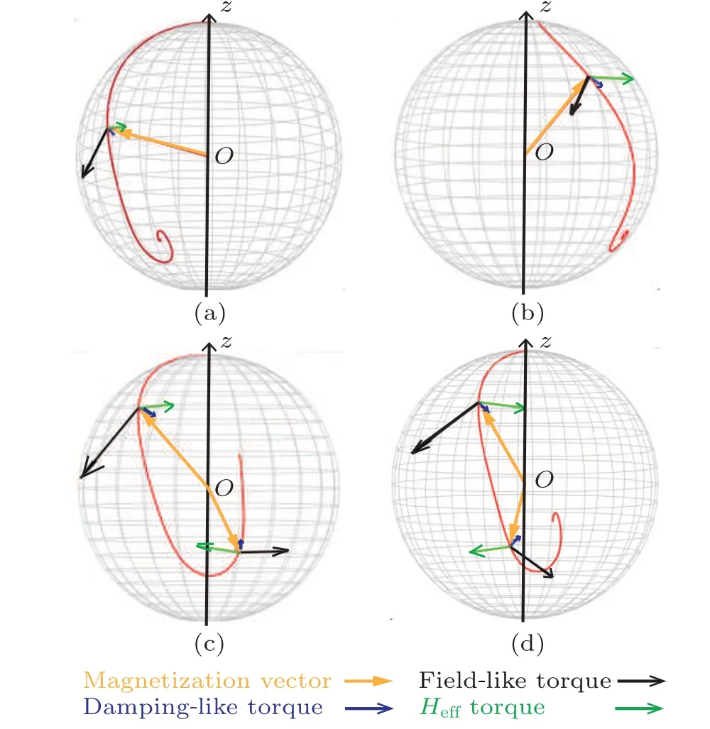
Fig. 3. Trajectories of magnetization vector and key torques in switching process: ((a), (b))unipolar switching for J=6×10¹¹ A/m2 and((c), (d))bipolar switching for J = 7.5×10¹¹ A/m2. Here other torques are not shown for the clarity. It is seen from panels(c)and(d)that the Heff torque has+z component and-z component,respectively,which are mainly contributed by the bias field(Hbias). Here we only show the trajectories for the case of starting point mz =1, which are highly symmetric with respect to those for the case of starting point mz=-1.
It is important to mention that the role of the bias field becomes significant only when the current density is sufficiently large. This conclusion can be explained by Fig. 4(a), where a non-zero bias field induces an effective torque to pull the magnetization vector back, leading to bipolar switching. In contrast,the effect of the bias field is negligible in the case of unipolar switching as shown in Fig. 4(b). The difference between Fig.4(a)and Fig.4(b)is attributed to the various values ofxcomponent magnetization(mx). Specifically,sinceHbiasis aligned to the +yaxis, thezcomponent effective torque is contributed by±γμ0mx×Hbias. Stronger current density leads to largermx(see Fig.4(a)),and hence more easily drives the magnetization vector towards thezaxis.
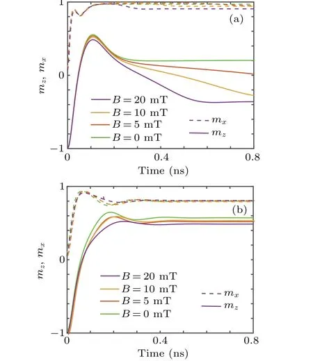
Fig. 4. Influence of the bias field on the magnetization switching for (a)bipolar switching and(b)unipolar switching.
The influence of key parameters on the switching mode is further discussed. Figure 5 shows the phase diagram of the final-statemzas a function ofλFL/λDLandJ. Overall, the bipolar switching occurs when both the current density and the field-like torque are large enough. In this case, the combination of stronger field-like torque and larger current density causes magnetization vector to approach in-plane direction, favoring the bias-field-induced torque, as illustrated by Figs. 3(c) and 3(d). On the other hand, the unipolar switching is obtained in a relatively narrow range of parameters,where the field-like torque suppresses the other factors and leads to the precession of the magnetization vector as shown in Figs.3(a)and 3(b).
The proposed mechanism of the magnetization switching is also validated through micromagnetic simulation. Here the Dzyaloshinskii–Moriya interaction (DMI) is further considered, since it is widely reported to exist in SOT devices.Micromagnetic simulations are performed by the OOMMF package. The MTJ diameter is changed to 100 nm for constructing the multi-domain scenario as distinguished from the macrospin model. Other magnetic parameters are in consistence with those used in macrospin simulation. Both the unipolar and bipolar switching are implemented with the appropriate parameter settings, no matter whether the DMI strength is zero or non-zero. Typical results for non-zero DMI(with a DMI magnitude of 0.3 mJ/m2and an exchange stiffness of 5×10-11J/m) are shown in Fig. 6, where the magnetization switching is completed through magnetic domain dynamics. However,the DMI has a dramatic influence on the characteristic of the magnetization switching. The unipolar switching disappears in the case of strong DMI (not shown here). Nevertheless, we find that the unipolar switching can be recovered by increasing the exchange stiffness(e.g.it is increased to 5×10-11J/m in Fig.6)or reducing the bias field.The reason may be that the uniformity of the magnetization is enhanced.
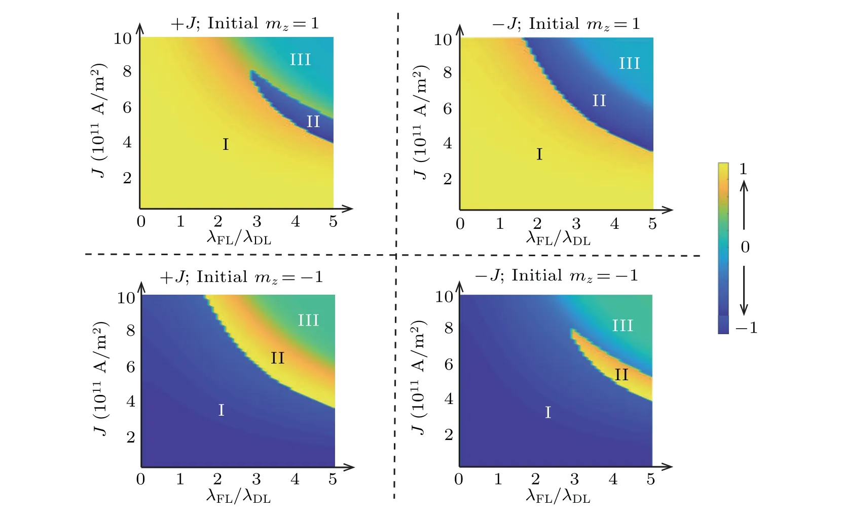
Fig.5. Phase diagram of mz as a function of λFL/λDL and J. Regions I,II,and III indicate,respectively,no switching,unipolar switching,and bipolar switching.

Fig. 6. Typical simulation results of micromagnetic configuration for the proposed switching mechanism, with the applied SOT current densities for unipolar switching and bipolar switching being J=4.5×10¹¹ A/m2 and J=5.8×10¹¹ A/m2,respectively,and SOT current withdrawn at 0.5 ns.
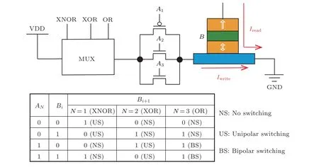
Fig. 7. Reconfigurable logic circuit using the proposed mechanism of magnetization switching. Here inputs are transistor gate voltage level(AN)and MTJ state in current cycle(Bi),and output is MTJ state in the next cycle(Bi+1).
Benefiting from the proposed switching scheme, the reconfigurable logic circuits can be flexibly designed. A typical example is shown in Fig. 7. Three transistors with different sizes are used as the selection switches for various logic functions. One of three transistors is activated by MUX for generating a write current whose amplitude is in the range of unipolar or bipolar switching.As a result,the specific logic function can be implemented and reconfigured as indicated in the truth table of Fig.7.
4. Conclusions
In summary,we have proposed a novel switching scheme for the perpendicular-anisotropy SOT device. The switching mode of the device can be transformed between the unipolar type and bipolar type,only by tuning the amplitude of the current density. For the unipolar switching, the strong field-like torque mainly governs the magnetization dynamics. For the bipolar switching, the bias field and field-like torque jointly determine the polarity of the magnetization switching. Our proposal can breed a multifunction SOT device, especially is suitable for the design of the reconfigurable memories and circuits.Furthermore,the presented theoretical work can provide guidance and reference for the future experiments.
Acknowledgements
Project supported by the National Natural Science Foundation of China (Grant Nos. 62171013 and 61704005),the National Key Research and Development Program of China(Grant Nos.2021YFB3601303,2021YFB3601304,and 2021YFB3601300),the Beijing Municipal Science and Technology Project, China (Grant No. Z201100004220002), and the Fundamental Research Funds for the Central Universities,China(Grant No.YWF-21-BJ-J-1043).
猜你喜歡
課堂內(nèi)外·小學版(低年級)(2024年5期)2024-06-07 17:35:28
課堂內(nèi)外·小學版(低年級)(2022年4期)2022-06-24 09:47:10
課堂內(nèi)外·小學版(低年級)(2022年5期)2022-04-29 05:13:57
Acta Mathematica Scientia(English Series)(2020年5期)2020-11-14 09:40:48
公民與法治(2020年3期)2020-05-30 12:30:00
金橋(2018年10期)2018-10-09 07:27:44
中國自行車(2018年8期)2018-09-26 06:53:08
Acta Mathematica Scientia(English Series)(2016年6期)2017-01-21 05:31:08
電影(2015年7期)2015-12-24 01:36:04
Acta Mathematica Scientia(English Series)(2015年6期)2015-02-10 08:37:29
- Chinese Physics B的其它文章
- Design of vertical diamond Schottky barrier diode with junction terminal extension structure by using the n-Ga2O3/p-diamond heterojunction
- Evolution of the high-field-side radiation belts during the neon seeding plasma discharge in EAST tokamak
- Phase-matched second-harmonic generation in hybrid polymer-LN waveguides
- Circular dichroism spectra of α-lactose molecular measured by terahertz time-domain spectroscopy
- Recombination-induced voltage-dependent photocurrent collection loss in CdTe thin film solar cell
- Development of ZnTe film with high copper doping efficiency for solar cells