
Design of improved compact decoupler based on adjustable capacitor for EASTICRF antenna
2022-02-15 11:08:58GenCHEN陳根YuzhouMAO毛玉周ShuaiYUAN袁帥YanpingZHAO趙燕平HuaYANG楊樺XinjunZHANG張新軍ChengmingQIN秦成明YanCHENG程艷andYongshengWANG王永勝
Plasma Science and Technology 2022年1期
Gen CHEN (陳根), Yuzhou MAO (毛玉周), Shuai YUAN (袁帥),Yanping ZHAO (趙燕平), Hua YANG (楊樺), Xinjun ZHANG (張新軍),Chengming QIN(秦成明),Yan CHENG(程艷)and Yongsheng WANG(王永勝)
Institute of Plasma Physics, Chinese Academy of Sciences, Hefei 230031, People’s Republic of China
Abstract The Ion Cyclotron Radio Frequency (ICRF) heating antenna on EAST adopts a decoupling device to constrain power coupling among the radiation straps, which was discovered shortcomings such as long size, poor contact, and etc.In order to improve these weak points, a new type decoupler with terminal-loaded tunable capacitor is designed to replace the previous design.Besides the capability of the tunable admittance parameters of decoupler, the withstand voltage of the capacitor is the most significant consideration for working under high power.Therefore, the theoretical analysis carefully elaborates the capacitor withstand voltage, and the detailed analytical equations and criteria for design are given.After the comparative analysis of theoretical calculation and 3D simulation results, the decoupler design scheme is finalized.The capacitor-loaded decoupler has been successfully adopted for ICRF antenna at port N on EAST,and achieved the optimization of adjacent port isolation from ?22 to ?58 dB at 37 MHz without plasma to restrict mutual coupling.The new design of the decoupler has greatly improved its compactness and automatic adjustment performance, and could be good solution for the decoupling network of ICRF antennas.
Keywords: decoupler, ICRF, adjustable capacitor, EAST
1.Introduction
The Ion Cyclotron Radio Frequency (ICRF) heating antenna adopts the design of multi-radiation straps, which results in a strong power coupling between the straps [1–7].To restrain such power coupling,variable decouplers have been developed in the world tokamak machines[8–13],and a decoupler based on the T-shape shorted stub was used on EAST [14–17].However, during the experiment, it was discovered that the short-circuit type with piston had shortcomings such as long size, difficult to adjust electrical length, poor contact of the short-circuit finger which leads to easy burning out etc.Therefore, it is planned to adopt a terminal-loaded tunable capacitor solution to shorten the length of the stub and facilitate adjustment,and the design of none short-circuit contact finger can avoid the problem of poor contact and burnout.
The design of a decoupler with terminal-loaded tunable capacitors should meet the requirements of mutual coupling suppression on EAST antennas, which works under the pressurized atmosphere of the transmission line.By changing the capacitance value, the imaginary part of non-diagonal term of Y parameter of the decoupler is supposed to achieve∣YT12/T21∣ ≤5 × 10?4S [16].In addition, the compactness and feasibility of the structure, the withstand voltage and the tunable range of the capacitor and other factors also need to be considered during the process of system design.
Three significant aspects are elaborated: T-shape stub with tunable capacitor design, simulation analysis and physical test.Section 2 introduces the theoretical derivation of the admittance matrix of the decoupling device, the relationship among the capacitor voltage and the capacitance value, and so on.Section 3 builds a simulation model based on the design parameters and discusses the simulation results.Section 4 shows the test results of the developed system without plasma.Finally, there is a conclusion of the whole design and tests.
2.Design analysis of T-shape stub loaded with tunable capacitor
Besides the tunable admittance parameters of decoupler, the withstand voltage of the capacitor is the most significant consideration for decoupler to work under high power.Therefore, based on the microwave engineering theory, the calculation model of capacitor loaded decoupler is constructed, and the capacitor working voltage and other performance parameters are deduced theoretically,which will be the foundation of the parameter’s selection of decoupler.
2.1.Y matrix of decoupler
Based on the original design [16], only the change of the introduced part of capacitive loading needs to be considered.Two-port network design with T-shape structure is applied on the decoupler.One of the ports is loaded with a terminal short-circuit tunable vacuum capacitor, as shown in figure 1(a).The T-shape stub loaded with tunable capacitor circuit used in decoupler can be equivalent to a two-port network cascaded by three parts,as shown in figure 1(b).The cascaded three parts are transmission lineL,1L2and T-shape stub respectively, where the ABCD matrix of transmission lineL1andL2can be expressed as:
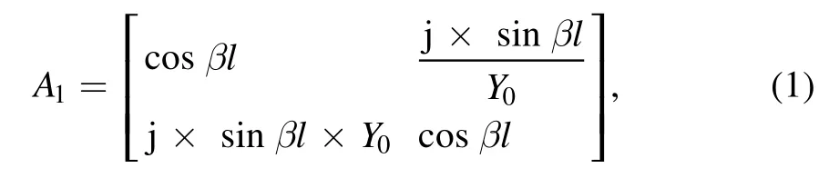
where,βis phase constant,lis the length of transmission lineL1andL2.Because of symmetrical design,L1=L2=l.Y0is the characteristic admittance of transmission line.
The ABCD matrix of part 2, i.e.T-shape stub, is:whereYdcan be expressed as [18]:
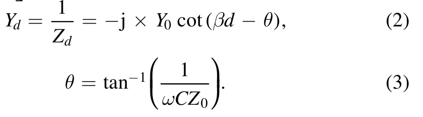
Among them,ZdandYdare the impedance and the admittance of the T-shape stub,θis the equivalent phase of the capacitor,ωis the operating angular frequency,Cis the capacitance of the capacitor.
According to microwave transmission theory, the ABCD matrix of decoupler can be expressed as:A=A1×A2×A1,and according to the conversion relationship of Y matrix and ABCD matrix, the Y matrix of decoupler can be derived as:
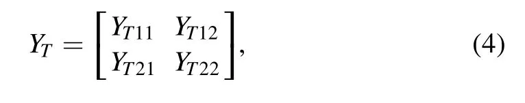
where

Therefore, the diagonal admittance of decoupler is determined by the equivalent phase of the terminal-loaded capacitor, which is the foundation for the decoupler to perform the mutual coupling suppression.
2.2.Operation voltage Vc of capacitor
When the capacitor is loaded at the short-circuit end of the T-shape stub, the withstand voltage and the tunable capacitance value need to be considered for high-power operation and antenna decoupling.The voltage at both ends of decoupler is:Vm=[V1V2],then, the current can be expressed as:[I1I2] =YT×Vm.According to the relationship between ABCD matrix and voltage-current,it can be deduced thatVdis as follow:
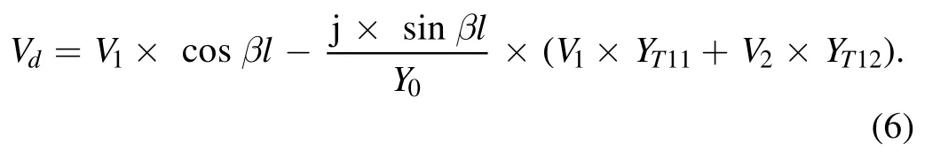
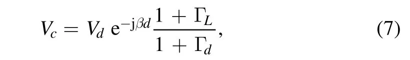
T-shape stub with terminal loaded capacitor can be expressed as figure 2,dis the fixed length of transmission line before loaded capacitor,Z0is characteristic impedance of transmission line.The voltage of loaded capacitor can be sustained by the voltage propagation equations of a terminated transmission line [18], which is:
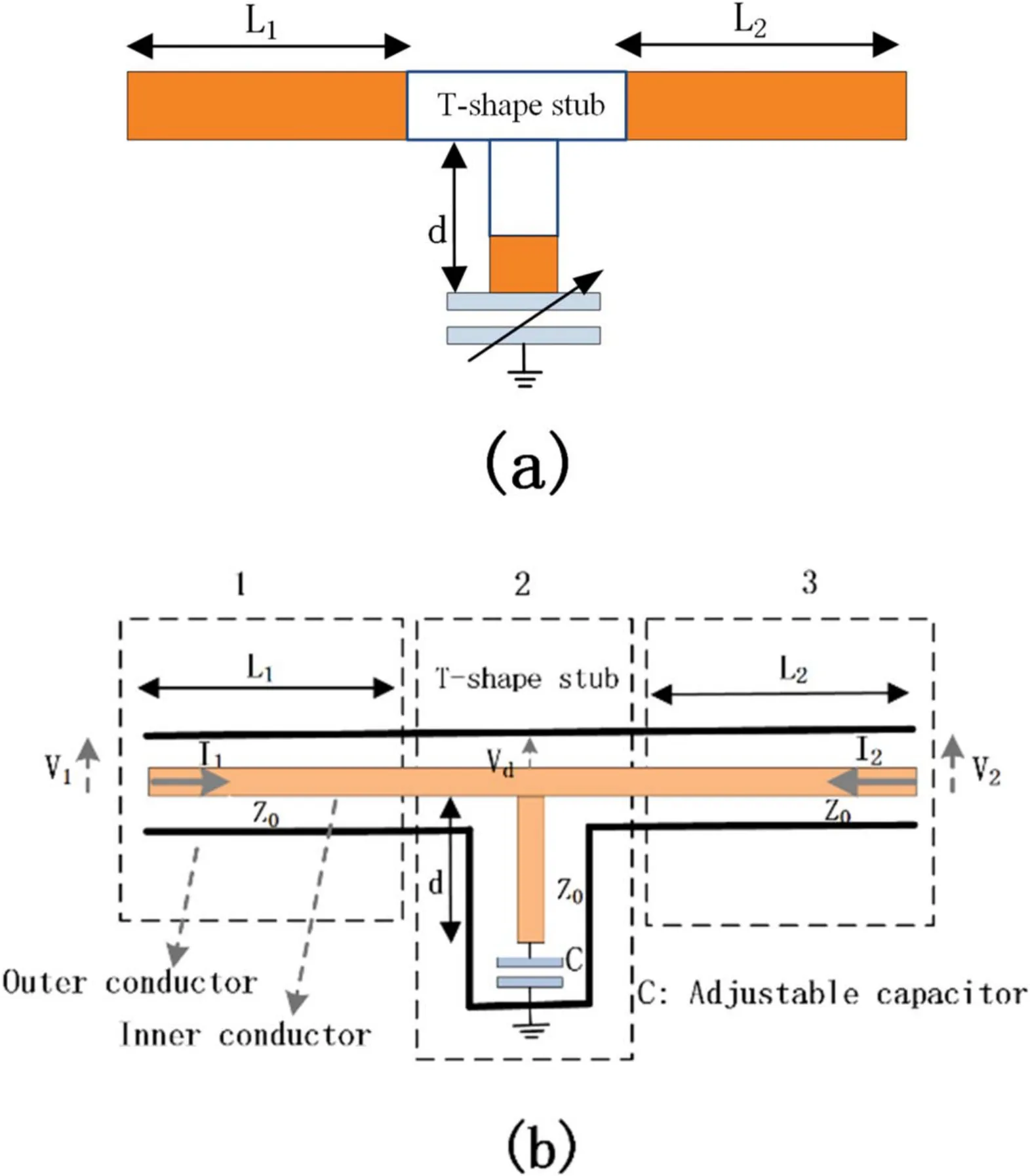
Figure 1.(a) Equivalent model of decoupler, (b) equivalent circuit of decoupler.
2.3.Parameter selection of tunable capacitor
Based on equations (4) and (7), the known parameters and conditions can be brought in to design the withstand voltage and capacitance value of the tunable capacitor.According to the design requirements and test conditions of ICRF antenna,the parameters already known are as follows:
(1) Operating frequency =f37 MHz;
(2) Design requirements according to experimental statistics [16]:∣ Im(YT21) ∣ ≤5 × 10?4S;
(3) Length selection of T-shape stub:L1=L2=
(4) Port voltage at the hard-fed connection between T-shape stub and ICRF antenna:V1=V2=30 kV;
(5) According to tunable capacitor selection manual [19],the operating voltage amplitude of the capacitor:∣ ∣≤Vc30 kV, and the range ofCis: 60 pF ≤C≤1000 pF,so as to ensure the compactness of branchd.
Put condition (3) into equation (4) to derive:
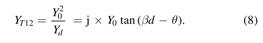
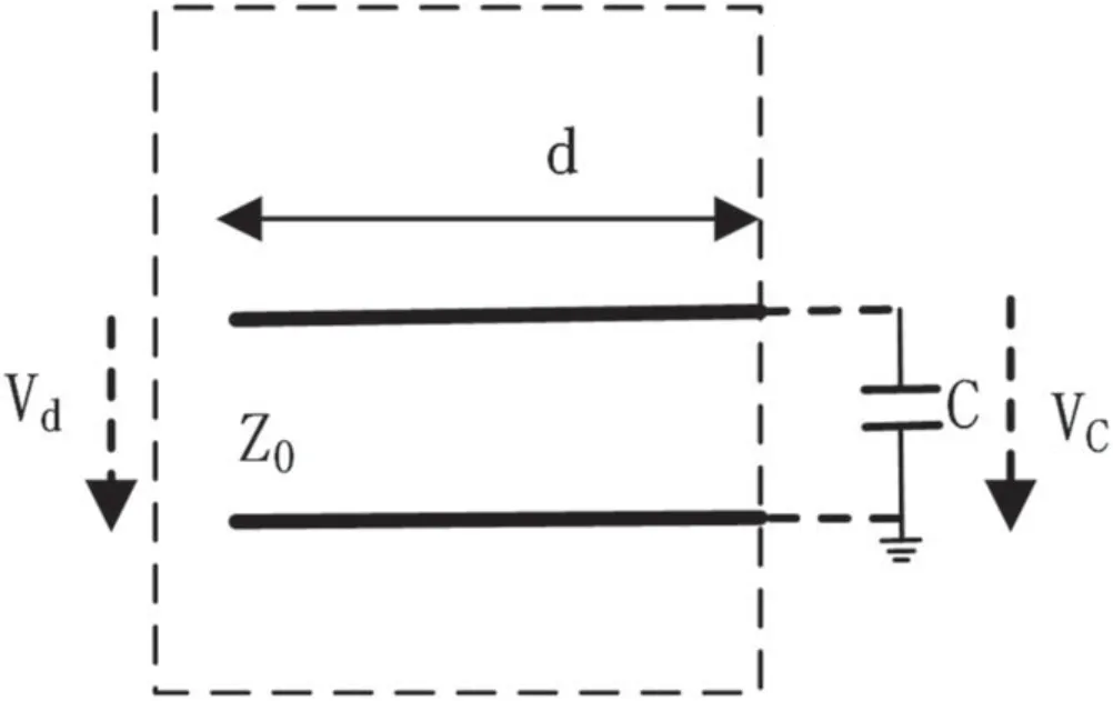
Figure 2.Diagram of the T-shape stub.
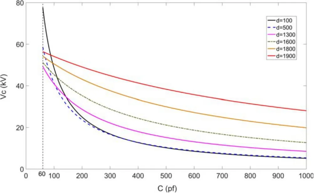
Figure 3.Relationships between voltageVc of capacitor and capacitance ofC.
According to equation (7), it can be deduced that:
To satisfy design requirement (2), the range of tan (βd?θ)can be derived from equation (8) that:

Taking three significant digits after the decimal point,atan (0 .025) ≈0.025, atan ( ? 0 .025) ≈?0.025, and tan function takesπas the period, then solve equation (10) to obtain:? 0 .025 +n×π≤βd?θ≤0.025 +n×π, n is an integer.
According to known condition(5),the range of capacitor C is: 60 pF ≤ C ≤1000 pF,the equivalent electric phase can be derived: 0.0858 ≤θ≤0.9618.In order to makedlength of T-shape stub as compact as possible,the value ofnis set to be 0, so:

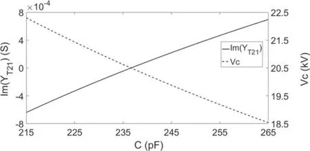
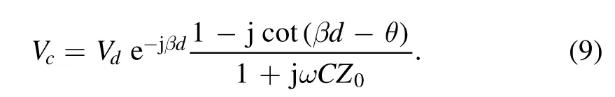
Figure 4.AdmittanceYT12 and voltageVc with different capacitance C of the capacitor.
According to equation (9), the voltage of the tunable capacitor can be calculated under different values ofd, as shown in figure 3.It is shown that the absolute value of capacitor voltageVcdecreases asCincreases, i.e.when the capacitance value of the tunable capacitor is larger, the voltages withstand condition of the capacitor itself will be significantly improved.
However, when the capacitance valueCof the tunable capacitor is greater, in order to achieve the corresponding parallel admittanceYT21required,the length ofdwill become shorter, and the structural implementation will become more difficult.TakingYT21into account, the working parametersd=450 mm, 220 pF ≤C≤260 pF are determined.At this time, the tunable range of T-shape stub is∣ Im(YT21) ∣< 5 × 10?4S,and the capacitance voltageVcis 19–22 kV, as shown in figure 4.
3.Cross-check with 3D simulations
According to these parameters, the capacitor CKTB1000/35/25 produced by Kunshan Guoli Electronic Technology Co.,which can achieve the tunable capacitance of ?60 1000 pF with the maximum voltage of 30 kV, is selected [19].Simulation models are built based on this capacitor, as shown in figure 5.Through the optimization of the lengthdand capacitorC,the result achieved shows that when =d450 mm, and 163 pF ≤C≤183 pF, it can realize the design require ments of capacitor voltageVc≤30 kV,and Im(YT21) can be tune d within∣ Im (YT21) ∣ ≤5 × 10?4S,as shown in fgiure 6.The∣ Im(YT21) ∣< 5 × 10? 4S.capacitor voltage is 22.6 kV ≤Vc≤23.7 kV with the
In order to make ( )YImT21meet the tunable requirement of(∣ Im (YT21) ∣ ≤5 × 10?4S) ,there are differences between the analytical calculation results shown in figure 4 and the 3D model simulation results shown in figure 6.The results of analytical calculation showed that =d450 mm and the tunable range of capacitanceCwas 220 pF ≤C≤260 pF with the operating voltage of 19 kV ≤Vc≤22 kV.However, the results of 3D simulation showed that =d450 mm and the tunable range of capacitanceCwas 163 ≤ ≤CpF 183 pF with the operating voltage of 22.6 kV ≤Vc≤23.7 kV.The reason for the difference is that there is parasitic capacitance and inductance inside and outside the capacitor.In figure 5,the lumped capacitor is set between the capacitor and the outer conductor and there is also an electric field distribution,which induces the additional parasitic capacitance and inductance.In addition, it can also be found that the influences of other parasitic factors, such as parasitic capacitance and inductance introduced by the discontinuity of capacitor connector, have caused the appeal deviation.As a result, the actual withstand voltage of the capacitance maybe exceed the calculated value, which should be noted in experiments.In practice, after the capacitor is adjusted to the decoupling working point,its capacitance can be measured again to check its withstand voltage.
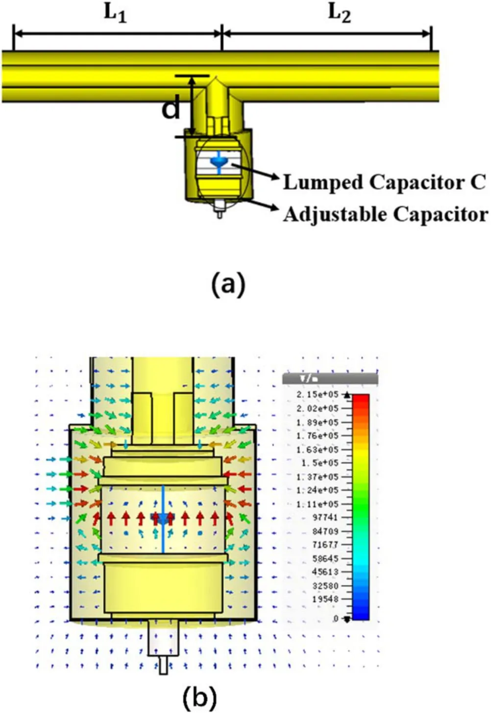
Figure 5.(a) 3D modeling of T-shape stub loaded capacitor, (b)electric field distribution of loaded capacitor in the T-shape stub.
4.Test of decoupler
Considering the achievability of the structure of d-length,theoretical calculation parameters adopted finally are:L1andL2take 1/4 wavelength of 2143 mm,dis 450 mm, and the model of capacitor is CKTB1000/35/250.The test adapters are selected at the ports of T-shape stub connector, as shown in figure 7(a).From the perspective of structural size, the previous design of the sliding stub is ~5 m long,as shown in figure 7(b), and tune of electrical length is achieved by mechanical sliding of short-circuit terminal.When the size is too long, it is quite difficult to guarantee the concentricity effectively.So, there is an obvious risk of damage to the short-circuit contact fingers with high-power operation, as found in previous experiments.Besides, the application of vacuum capacitors effectively reduces the size of the decoupler, which has obvious advantages when building the decoupling network for an ICRF multi-strap antenna.
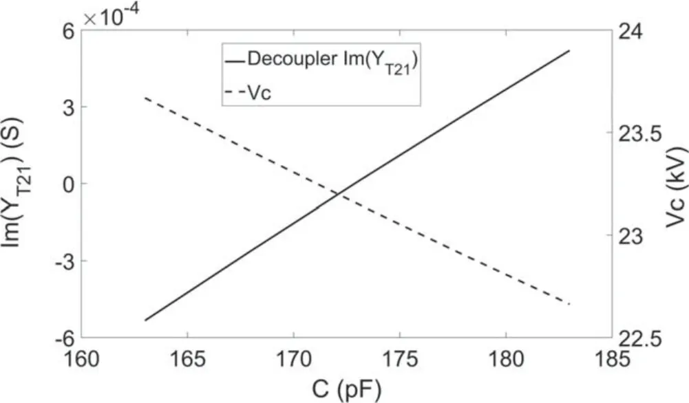
Figure 6.Working diagram of capacitor voltageVc, admittanceYT12 and capacitorC at the operating frequency of37 MHz.
Compared with T-shape stub,the difference of decoupler isL1/2?450 mm in transmission line length at two ports,so the decoupler admittance can be obtained by measuring T-shape stub and transforming it by microwave networks analysis, as shown in figure 8.The test results of parallel admittance ( )YImT21of decoupler meet the required tunable range of(∣ Im (YT21) ∣ ≤5 × 10?4S) .In the working region of capacitor, there is a certain linear relationship between capacitance regulation and admittance change, which is in line with the theoretical analysis in section 2.In addition,the admittance of the decoupler has a very wide tune range,which means that it can be used as a general design solution for various ICRF antennas.However, from the theoretical analysis, it is known that the choice of the working capacitance directly determines the working voltage and high-power stability of the capacitor, which needs to be considered in actual usage and has been described in the above theoretical analysis and analytical solution.
In EAST 2021 experiments, the decoupler with this new design is adopted for two straps ICRF antenna at port N.The scattering parameterS21of the two ports without plasma tested by a vector network analyzer is optimized from –22 to–58 dB at the working frequency of 37 MHz, as shown in figure 9.Due to the influence of plasma discharge parameters,the adjustable capacitance will be fine-tuned between shots for compensation.Usually, the fine-tuning range is very fine.For coaxial adjustable capacitors, it does not exceed the adjustment range of one circumference.Then a limit signal can be used to overcome the difficulty of coaxial adjustable capacitor in capacitance calibration.Based on above reasons,this design of capacitor-loaded decoupler satisfies the requirements of compactness and remote adjustability for ICRF decoupling network on EAST.

Figure 7.(a) Capacitor-loaded T-shape stub, (b) T-shape stub with mechanical sliding of short-circuit terminal.
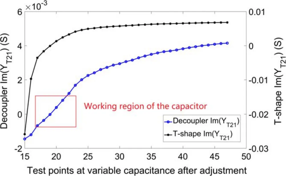
Figure 8.Test data of /YT T12 21 of T-shape stub and decoupler.
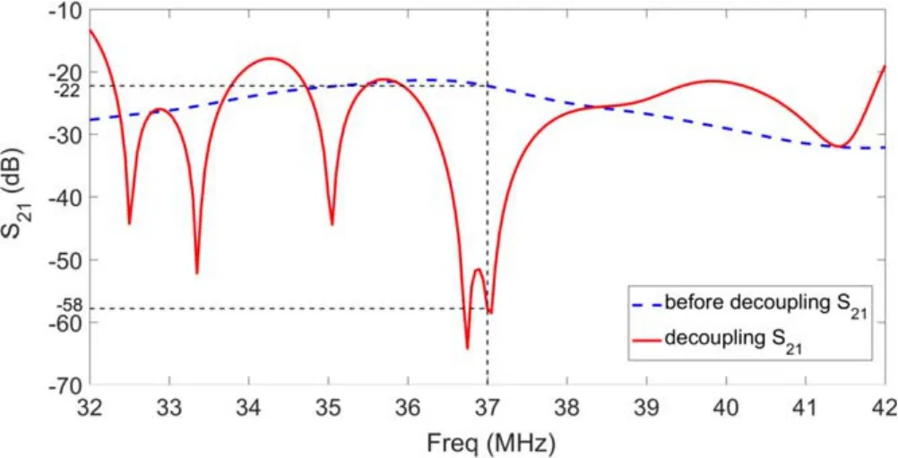
Figure 9.Scattering parameter S21 before and after decoupling at 37 MHz.
5.Conclusions
During the design of capacitor-loaded decoupler, those factors,such as the adjustable range of parallel admittance, the compactness and feasibility of the structure, and the voltage and adjustable range of the capacitor, have been taken into considerations.The theoretical analysis carefully elaborates the capacitor withstand voltage,which is the most significant aspect for high power operation of decoupler,and the detailed analytical equations and criteria for design are given.The test results show that the imaginary part ofYT21covers∣ Im (YT21) ∣ ≤5 × 10?4S.The capacitor-loaded decoupler has been successfully adopted for ICRF antenna at port N on EAST,and achieved the optimization from ?22 to ?58 dB at 37 MHz without plasma.The new design of the decoupler has greatly improved its compactness and automatic tune performance,and could be good solution for the decoupling network of ICRF antennas.
Acknowledgments
This work is supported by National Natural Science Foundation of China (No.11775258).
猜你喜歡
大江南北(2022年11期)2022-11-08 12:04:18
小學(xué)生學(xué)習(xí)指導(dǎo)(高年級(jí))(2021年10期)2021-11-02 05:32:12
科學(xué)與財(cái)富(2021年34期)2021-05-10 16:24:21
汽車觀察(2018年12期)2018-12-26 01:05:44
Journal of Oceanology and Limnology(2018年3期)2018-07-11 01:58:38
寶藏(2018年6期)2018-07-10 02:26:38
Journal of Oceanology and Limnology(2018年2期)2018-05-07 06:07:52
知識(shí)經(jīng)濟(jì)·中國(guó)直銷(2017年11期)2017-11-28 05:32:34
中國(guó)西部(2017年4期)2017-04-26 03:49:43
安徽文學(xué)(2016年7期)2016-12-14 01:30:44
 Plasma Science and Technology2022年1期
- Plasma Science and Technology的其它文章
- W fuzz layers: very high resistance to sputtering under fusion-relevant He+irradiations
- Discharge and post-explosion behaviors of electrical explosion of conductors from a single wire to planar wire array
- Influence of anode temperature on ignition performance of the IRIT4-2D iodine-fueled radio frequency ion thruster
- Experimental study on plasma actuation characteristics of nanosecond pulsed dielectric barrier discharge
- A novel double dielectric barrier discharge reactor with high field emission and secondary electron emission for toluene abatement
- Plasma activated water prepared by different plasma sources: physicochemical properties and decontamination effect on lentils sprouts