
A neural network-based commutation optimization strategy and drive system design for brushless DC motor①
2022-01-09 02:08:42LiuYuxiang劉宇翔YaoZhaolinYuanFangLiuMingLiXiangZhangXu
High Technology Letters 2021年4期
Liu Yuxiang(劉宇翔),Yao Zhaolin,Yuan Fang,Liu Ming,Li Xiang,Zhang Xu
(State Key Laboratory on Integrated Optoelectronics,Institute of Semiconductors,Chinese Academy of Sciences,Beijing 100083,P.R.China)
Abstract
Key words:brushless DCmotor,senseless control,back electromotive force,neural network,hardware implantation,field programmable gate array(FPGA)
0 Introduction
Sensorless brushless direct current motor(BLDC motor)has a simple structure,small size,light weight due to sensor free compared with normal BLDC motor,thus is widely used among household appliances and aeromodelling where volume and weight are strictly limited[1].Current commutation strategies for sensorless BLDC include the zero-crossing detection method based on back electromotive force(back-EMF)[2],triple frequency harmonic method based on back-EMF[3-4],fuzzy control method[5-8],etc.With the development of neural network,motor commutation strategies based on neural network[9-12]have also been proposed.Among these methods,the zero-crossing detection method based on back-EMF has the most extensive application due to its simplicity and usability.
In the conventional back-EMF based zero-crossing detection method,as the result of the algorithm,there will be a deviation between the predicted commutation point and the ideal commutation point[13-15]when the motor accelerates or decelerates,resulting in jittering and increasing in motor power consumption.However,most of the conventional optimization strategies only compensate for the commutation error generated when the motor is at a stable speed,and there is no targeted research on the commutation error generated when the motor is accelerating or decelerating.Also,the conventional neural network prediction is generally performed online through a host personal computer(PC)or digital signal processing(DSP)module,which will be limited by the transmission time of the signal and the performance of the DSP,and,therefore,limits the available speed range of the motor.When the motor speed is too fast,the commutation point can not be calculated in time,causing the motor failing in commutation and operating abnormally.
To solve the above problem,this paper proposes a neural network based back-EMF optimization algorithm and quantifies the influence of motor acceleration or deceleration on the commutation point by introducing motor acceleration into the network.At the same time,this article builds a complete BLDC motor drive system based on the GD32F103 micro control unit(MCU),and uses Xilinx’s XC7A35T field programmable gate array(FPGA)to implement the neural network hardware acceleration module.The proposed network performance is tested and verified.The experimental results show that the proposed commutation strategy can improve the system stability effectively,and reduce the system power consumption by 11.7%.
1 Proposed method
1.1 Conventional BLDC motor commutation strategy
When motor is working,the change of back-EMF is calculated by electromagnetic induction theory and shown as Fig.1,due to the armature winding cutting the magnetic line in the stator magnetic field.When the motor rotates in a constant speed,the time commutation occurs after detecting the zero-crossing event(hereinafter called delay-time)should equal to the time from the last commutation point to the zero-crossing event(hereinafter called wait-time)under ideal conditions,thus the sensorless commutation can be realized by measuring the wait-time and then estimating the delay-time with it.

Fig.1 Relationship between back-EMF and working phase
However,when the motor speed changes,the fluctuation of the motor will cause a large gap between wait-time and delay-time,introducing commutation errors as shown in Fig.2[9].The generated commutation error will result in fluctuations,low system stability and high power consumption.Also,the current spikes generated during commutation may also be dangerous to the control system.In worst-case scenario,serious commutation errors may even cause operational errors such as stalling and reversing,which greatly affects the normal operation of the motor.
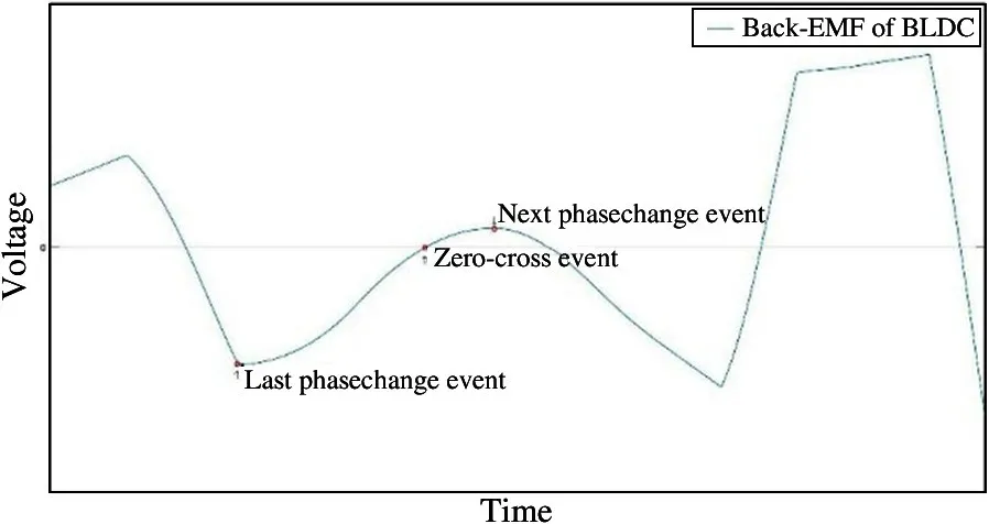
Fig.2 Back-EMF waveform when BLDC motor accelerates
1.2 Proposed method
To achieve an accurate prediction of the commutation point when the motor speed changes,this paper proposes an optimization strategy based on the neural network on the basis of the conventional back-EMF commutation method.The input of the network includes the current acceleration of the motor to make an accurate prediction on the commutation point when the motor speed changes.The structure of the network is shown in Fig.3,in which the input is the wait-time,the average acceleration of the motor during the waittime,and the output is the delay-time.When determining the number of hidden layers and the number of nodes,in consideration of a large network may lead to a large calculation delay,which will limit the maximum motor speed(that is,the network calculation delay cannot exceed the delay time,otherwise the optimal commutation point will be missed),the final network structure includes two hidden layers,each with 5 nodes(shown in Fig.3).This article implements network training through the backpropagation(BP)method.
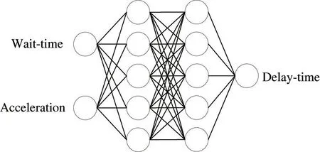
Fig.3 Structure of proposed BP neural network
2 Implementation and experimental results
2.1 Hardware test system
The diagram of the hardware test system is shown in Fig.4.The motor used in the experiment is the X2212 brushless DC motor of SUNNYSKY,which is mainly used in rotorcraft,and its parameters are shown in Table 1.Since the speed of the rotorcraft often changes rapidly and drastically when working,it is suitable to verify the proposed algorithm in this paper.This article also builds a BLDC motor drive control system based on the GD32F103K8U6 MCU(GigaDevice),which realizes the drive of the motor and serves as a data transmission platform between FPGA and PC.Since the algorithm is optimized on the basis of the conventional back-EMF method,the MCU needs to output a fixed sequence to make the motor reach a certain initial speed when starting,and use the neural network to predict the commutation point after that.The experimental system is shown in Fig.5.
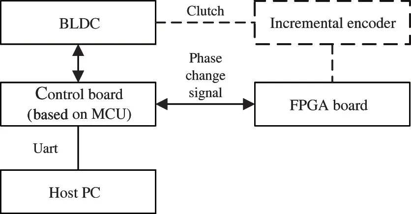
Fig.4 Brushless DCmotor hardware test system

Table 1 Parameters of the motor used in the experiment

Fig.5 Neural network prediction experiment platform
In the experiment,the incremental encoder is used(shown in Fig.4)to generate the ideal commutation signal as the training data of the network during the pre-experiment,and FPGA is used to decode output signal and transmit it to the host PC through the MCU,where the data is preprocessed and network training is completed.The encoder uses the incremental encoder E6B2-CWZ6Cfrom Omron,with a resolution of 2500P/R.The training data acquisition platform during actual testing is shown in Fig.6.
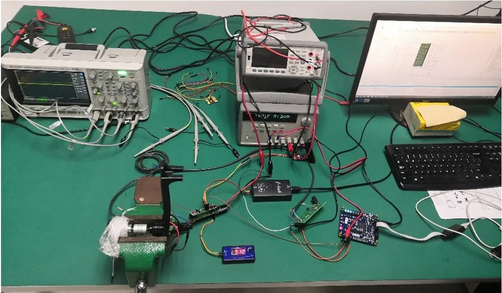
Fig.6 Neural network training data acquisition platform
When training the network,wait-timet1and delay-timet2can be acquired directly by receiving data,but the average acceleration needs to be calculated separately.The simplified diagram of motor operation process is shown in Fig.7.
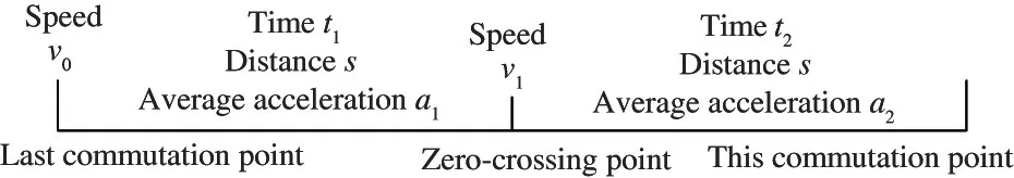
Fig.7 Simplified diagram of motor operation process in training
Here it can be assumed that the acceleration duringt1andt2can be seen as approximately constant.There are two reasons for this assumption.On the one hand,t1andt2are very short for multi pole pair motors.For BLDC motor,the number of commutations per minute should be equal to the speed per minute multiplied by the number of motor pole pairs and then multiplied by the number of commutation phases per pair.Taking the motor used in this paper as instance,when motor speed is 7000 rpm,the interval between each phase is about 204μs.On the other hand,it can be seen from Fig.1 that at the beginning oft1(the previous commutation point)and at the end oft2(the later commutation point),the back-EMF force on motor is only affected by the motor speed.As assumed above,the motor speed is approximately constant in these phases,thus the two commutation points have the same back-EMF force.Additionally,the back-EMF force at the commutation point is also the same,so int1andt2,the work of back-EMF on the motor is the same.According to the definition of work and acceleration formula in physics,the assumption that the average acceleration oft1andt2are the same can be obtained.
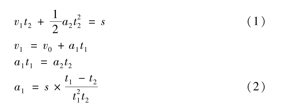
Based on the above conditions,a set of formulas can be derived(Eq.(1))and the acceleration could be calculated(shown in Eq.(2)after simplification).

2.2 FPGA-based neural network hardware accelerator design
Because the performance as well as the device resources of the MCU is not enough to realize the realtime calculation of the neural network,and in order to shorten the calculation delay to increase the available speed range of the system,FPGA is used to realize the hardware acceleration system of the neural network to meet the time requirements of the system.
The flow chart of the acceleration system is shown in Fig.8,which is composed of 4 sub-modules,including universal asynchronous receiver/transmitter(UART)module,pre-treatment module,neural network calculation module,and output module.To minimize the system transmission delay,the UART transmission rate in the system is set to 3 375 000 baud,so the 32-bit input information can be transmitted in 20μs.The fixedpoint design is adopted in the hardware accelerator,and the parameter format in the network is Q13.18.

Fig.8 FPGA-based prediction acceleration system
At the same time,because the delay-time is not known when usingtheproposed algorithmtopredict,the above acceleration calculation method can no longer be used,thus a new estimation method is proposed by using the last phase change point and the phase change point before it.The operation diagram of the motor is shown in Fig.9.The calculation formula and the result are shown in Eq.(3)and Eq.(4).
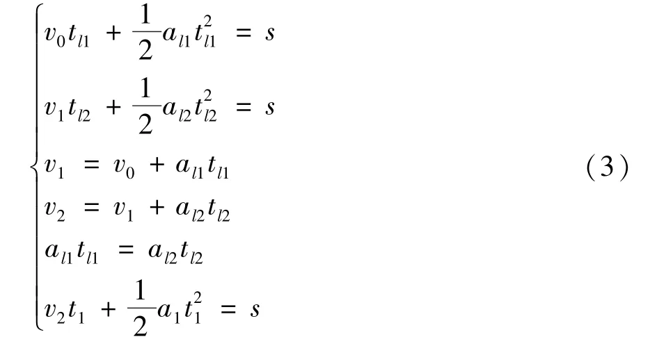
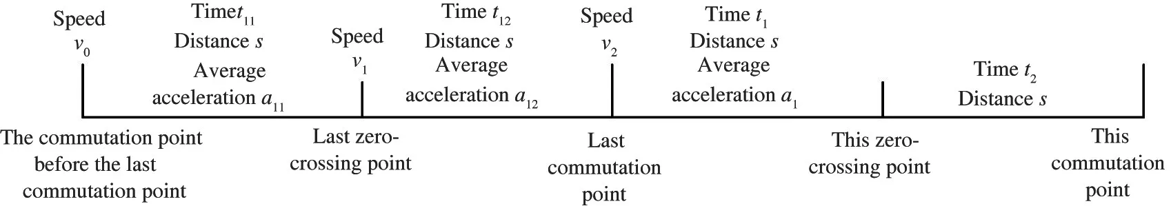
Fig.9 Simplified diagram of motor operation process in predicting

After getting delay-time,subtract it with the calculation and transmission delay provides the time that still needs to be delayed in the system.Then the system delays and outputs the commutation signal to the MCU to realize the commutation operation of the motor.The four modules of the FPGA hardware accelerator are at the same level,and with the sequential activation ensures that only one module is working,and the other three modules are in standby state to reduce power consumption of the system.
2.3 Experimental result
In experiments,the control method with sensor(incremental encoder),the conventional back-EMF control method,and the proposed commutation method based on the back-EMF neural network are tested and compared.Here the conventional back-EMF control method records wait-timet1by MCU,and calculates delay-timet2correspondingly.In this paper,t2equals 1/3t1,due to extra delays including calculation,transmission and other errors caused by non-ideal factors in practical application.This scale factor is derived from pre-experiment,where motor performance can be verified when the factor equals 2,1,1/2,1/3,1/4.The traditional back-EMF control method acts as the ablation study in the experiment.The proposed algorithm in this paper is based on the back-EMF control method,through which the measured parameters are sent to the network for training,and the control results are obtained to control the motor.
The online debugging function of the PC software is used to modify the input throttle of the motor accurately in the test,and the adjustment range is 1150-1600(corresponding to the speed range of 2000-7500 rpm).The performance of the motor under acceleration and deceleration is tested.Under acceleration,the waveform of the total current and total voltage of the motor system is shown in Fig.10.It can be seen that compared with the conventional back-EMF control method,the motor runs more smoothly under the sensor-based method and the proposed method,and the current and voltage fluctuations are minimized when the speed changes.The stability of the conventional back-EMF control strategy is poor,with severe fluctuations and even negative currents which might damage the drive system.

Fig.10 Total current(upper curve)and voltage(lower curve)during acceleration
In order to quantitatively compare the control performance of each control strategy,this paper also calculates the motor operating power under different control strategies and the result is shown in Table 2.The control method with sensor has the smallest commutation power.The power consumption of conventional commutation method is the highest due to its low stability.The proposed method has a low power consumption,which reduced by 6.9%compared with the conventional control strategy.
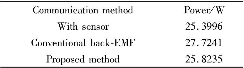
Table 2 Performance of each commutation strategy during acceleration
Similarly,when the motor is decelerating,the waveform of the total current and total voltage of the motor is shown in Fig.11.It can be seen that the conventional commutation method is very unstable when the motor speed changes drastically,and the motor current has severe fluctuations.The instantaneous maximum reverse current can exceed 10 A,which generates higher requirements for the safety of the system.
Table 3 shows the motor performance parameters under each commutation strategy when the motor is decelerating.The sensor-based control method and the control strategy proposed in this paper have low power consumption, while the conventional commutation strategy results in a large power consumption due to the current fluctuation during the commutation process.The proposed method in this paper can reduce the power consumption by 11.7%compared with the conventional back-EMF control method.
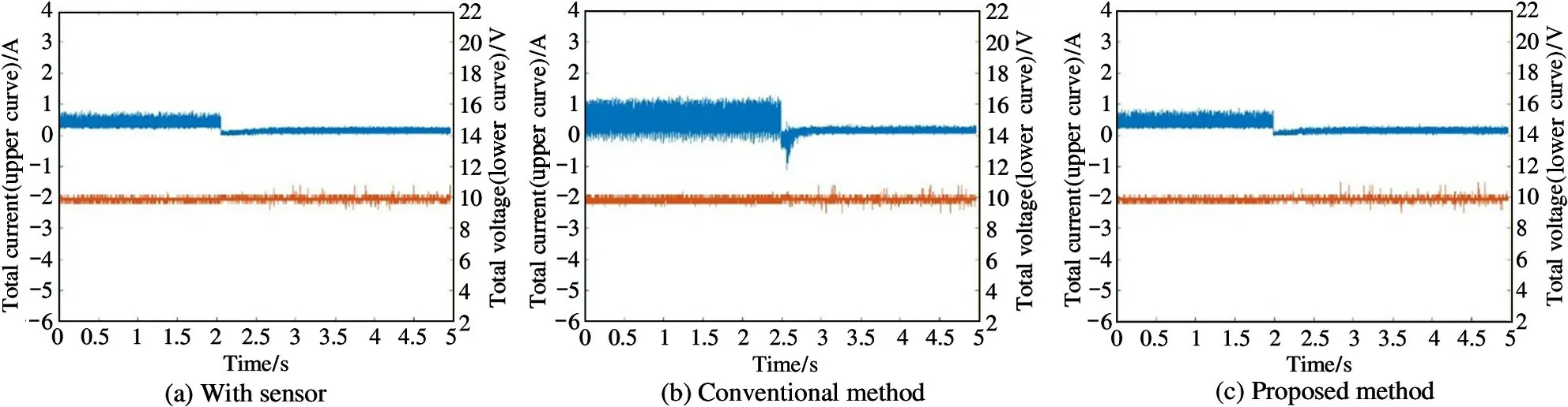
Fig.11 Total current(upper curve)and voltage(lower curve)during deceleration

Table 3 Performance of each commutation strategy during deceleration
At the same time,with the neural network acceleration system built in this article,the maximum support motor speed can reach 7500 rpm,which improves the motor application range.By comparing the speed range of the motor under each control strategy and the working platform shown in Table 4,it can be seen that the BLDC motor drive system and neural network hardware acceleration system implemented in this paper have a wide range of motor speed without online host PC or floating-point DSP(FDSP)unit.
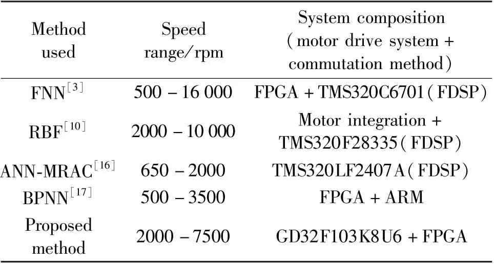
Table 4 Realization result comparison
3 Conclusions
In this paper,to solve the poor motor stability and high power consumption in the conventional back-EMF based on commutation strategy,a neural network based commutation strategy of the sensorless BLDC motor is proposed.Trained by the data acquired by incremental encoder,the proposed method is verified by the motor drive system built with the FPGA-based neural network hardware acceleration module.
The experimental results show that the proposed strategy can effectively improve the system stability.The current and voltage fluctuations caused by commutation error are minimized,thus power consumption during acceleration and deceleration is reduced by about 11.7%.Meanwhile,the system supports a maximum motor speed about 7500 rpm,which supports a wide speed range due to the FPGA acceleration module.
 High Technology Letters2021年4期
- High Technology Letters的其它文章
- A switching-based backstepping sliding mode control for space manipulator in presence of gravity variation①
- Protective effect of compressing arc extinguishing lightning protection device on superimposed lightning strikes①
- Wedge template optimization and parallelization of depth map in intra-frame prediction algorithms①
- CCD signal acquisition and optimal digital denoise technology①
- Study on spiral winding swimming motion control of a slender legless creature model①
- Dynamic control for the feed system of a robotic drilling end-effector①