
Design and verification of a broadband highly-efficient plasmonic circulator?
2021-03-19 03:20:14JianfeiHan韓建飛ShuZhen甄姝WeihuaWang王偉華KuiHan韓奎HaipengLi李海鵬LeiZhao趙雷andXiaopengShen沈曉鵬
Chinese Physics B 2021年3期
Jianfei Han(韓建飛), Shu Zhen(甄姝), Weihua Wang(王偉華), Kui Han(韓奎),Haipeng Li(李海鵬), Lei Zhao(趙雷), and Xiaopeng Shen(沈曉鵬),?
1School of Materials Science and Physics,China University of Mining and Technology,Xuzhou 221116,China
2School of Information and Control Engineering,China University of Mining and Technology,Xuzhou 221116,China
Keywords: plasmonic,circulator,spoof surface plasmon polaritons,ferrite
1. Introduction
Circulators are widely used in radar and radio communication systems, which are used to realize one-way transmission function.[1-4]They play an important role in avoiding mutual interference between the transmitted and received signals. They also play a critical role in protecting the signal source. There has been extensive theoretical and experimental research on microstrip line,strip line,and the waveguidesbased Y-junction circulators, which rely on the anisotropic permeability of YIG ferrite.[5-11]With the rapid development of modern science and an increasing demand of communication systems, different schemes have been proposed to realize circulators. In 2016, Liu et al. introduced magnetooptical materials into dielectric waveguides and proposed a four port circulator by exploiting the anisotropic permittivity of magneto-optical materials under the bias of external magnetic fields.[12]In 2019, Dmitriev et al. proposed a circulator based on the anisotropic permittivity of graphene materials under the bias of external magnetic fields.[13]Most of the circulator designs achieve one-way transmission by applying an external magnetic field to the gyroelectric or gyromagnetic material to break the symmetry of the permittivity or permeability tensor.[14-19]Non-magnetic material is also used to design circulators without using a magnetic field bias to break reciprocity.[20,21]These designs open up a way to design nonreciprocal devices based on different mechanisms.
Spoof surface plasmon polaritons(SSPPs)have received widespread attention at microwave frequencies,[22]whose properties are very similar to those of SPPs in the near-infrared and optical regions.[23,24]For example,SSPPs find similarities with SPPs in terms of dispersion relations,local field enhancement, sub-wavelength confinement and other characteristics.Shen et al. proposed a planar ultra-thin SSPPs waveguide that enables SSPPs to be transmitted along a curved, folded surface for a long distance.[25,26]This kind of planar guided wave structure has a strong field confining ability to SSPPs,and achieves low loss and high efficiency transmission. These works have greatly promoted the rapid development of plasmonic devices in microwave frequency region.[27-33]Recently,Pan et al. proposed a circulator which uses comb-like transmission lines to guide the signals.[34]The design is compact with insertion loss at about 0.5 dB in the frequency range of 10.6 GHz-11.5 GHz. It is still quite challenging to design a broadband and highly-efficient SSPPs based circulator and the physical mechanism of the working of plasmonic circulator needs to be clarified.
In this paper,we propose a wideband,low-loss and highly efficient plasmonic circulator. Structured metal stripes have been used as internal conductor of the circulator to guide the propagation of SSPPs. A static bias magnetic field has been applied to the ferrite and one-way transmission of SSPPs has been realized by using its anisotropy. The overall structure is completely symmetrical and has the same transmission and isolation performance once evaluated from different ports.The characteristic of the proposed plasmonic circulator has been verified through numerical simulations as well as experiments. At the same time, equivalent circuit model has been applied to evaluate the transmission, reflection and isolation characteristics of the plasmonic circulator.
2. Design and analysis
2.1. Plasmonic circulator design
The structure model of the plasmonic circulator is shown in Fig.1(a). The entire circulator consists of three SSPPs waveguides, two ferrite disks, two foams, and two ground planes. The thickness of the SSPPs waveguides is 0.018 mm and the substrate is F4B with thickness 0.1 mm and permittivity εr= 2.65. Two ferrite disks have been placed above and below the center conductor (triangle region) with radius R=6.5 mm, height h=2 mm. Yttrium-iron-garnet (YIG)-based ferrite has been used having a saturation magnetization of 4πMs=1850 Gs(1 Gs=10?4T),resonance line width of ΔH = 10 Oe (1 Oe=79.5775 A·m?1), and relative permittivity of εf=15. Two foam boards with hollow center have been used to fix the YIG ferrite disks and support the metal ground. The SSPPs waveguide structure and related dimensions are shown in Fig.1(b). Three waveguides with 120?rotational symmetry have been connected to the central conductor junction. Both sides of the SSPPs waveguides have been designed to have a blade-like metal structure and the transmission path is equal from all the ports. The CPW with the GND plane has been used as the feed of three ports. The transition part is composed of a gradient comb-shaped waveguide and flared ground on both sides,which improves the coupling efficiency of SSPPs. A transition has been designed which ensure impedance matching while transitioning from CPW to SSPPs mode. The length and width of the flared ground have been designed as L1=26 mm, L2=12 mm, and W =5 mm. The comb unit structure has the parameter of period p=5 mm,groove width a=2 mm,and groove depth h=4 mm.

Fig.1.Configuration of the proposed plasmonic circulator.(a)The structure model of the plasmonic circulator. (b)The structure diagram of the SSPPs waveguide and the corresponding structural parameters.

Fig.2. (a)S-parameters of the simulation(Sim.) and the equivalent circuit(Cir.) model when electromagnetic wave incident from port 1. S11(solid line)is the return loss,S21 (dash dot line)is the insertion loss,and S31 (dash line)is the isolation. (b)-(d)The Ez distribution of the electric field as incident from ports 1,2,and 3 at frequency of 8 GHz,respectively.
We have analyzed the transmission characteristics of the circulator after applying a magnetic field of H0=1750 Oe using CST Microwave Studio. Figure 2 shows the simulation results of circulator’s insertion loss, isolation, and return loss and the distribution of the electric field in z direction when the wave is incident from port1. From the simulation results(red curves) in Fig.2(a), it can be seen that the insertion loss is less than 0.5 dB in the frequency range of 6.0 GHz-10.0 GHz while the return loss and isolation are more than 12 dB. Due to the symmetric design of the circulator,no matter which port the signal is input from,we observed a consistent trend in all the S-parameter curves.
To visualize the performance of the circulator, we monitor the electric field at 8.0 GHz. Figure 2(b)shows the intensity distribution of the electric field(Ez)at z=0.5 mm plane above SSPPs waveguide when the signal is input from port 1.Same magnitude of electric field intensity at port 1 and port 2,indicates that the resonance modes of the ferrite cavity can effectively transfer the signal to port 2.In contrast to that,energy transmitted from port 1 to port 3 is very small,which indicates that the resonance modes of the ferrite cavity are blocking the signal to port 3.Figures 2(c)and 2(d)show the intensity distribution of the electric field(Ez)at the z=0.5 mm plane above the SSPPs waveguide when the signal is input from port 2 and port 3,respectively. The distribution of electric field in Fig.2 proves that the input and output ports show a perfect cycle in a sequence of 1 →2,2 →3,3 →1.
2.2. Equivalent circuit model analysis
In order to understand the working mechanism of the deigned plasmonic circulator, we have employed an equivalent circuit model. The model is represented by a series of LC circuits which helps analyze the performance of the circulator.[35,36]Equivalent circuit model has been widely used to analyze the working mechanism of absorber, filter, and circulator. Very recently it has also been used to analyze the transmission performance of SSPPs.[37-39]The LC circuit equivalent of plasmonic circulator is shown in Fig.3. In this model,the capacitor C is formed between the central conductor junction and the grounding plate, which is very important for broadband response of the circulator. The inductance L at the central junction is a function of ω,Ms,and H,which translates to L=L(ω,Ms, μ,κ). Ciis formed between each short stub and the metal ground,connected by inductance Li. When applying a uniform static magnetic field along z direction,the permeability tensor is given by


Fig.3. Equivalent circuit model of the proposed plasmonic circulator.
According to the impedance matrix theory of three ports nonreciprocal network,the eigenvalues of the impedance matrix are determined as a function of frequency and circuit parameters.[38,40]The non-reciprocal junction impedance matrix Z can be used to find its three intrinsic impedances. According to three-port network series and parallel rules,eigenvalue algorithm can be used to find the eigenvalues corresponding to the impedance or admittance.[41]Using the relationship between the three-port scattering coefficients and impedances,S11,S21,and S31are expressed as follows:

where z is the eigenvalue of the same-direction excitation,z+the eigenvalue of positive-phase excitation, and z the eigenvalue of negative-phase excitation.
The circuit model has been implemented in an advanced design software tool and the circuit model calculations have been matched with the simulation results. The S-parameter curves obtained by the equivalent circuit model are shown in Fig.2(a)(blue curves). The results show that in the frequency range of 6.0 GHz-9.0 GHz, the return loss and isolation are more than 11 dB while the minimum values are 50 dB and 35 dB,respectively.The S-parameters obtained from the simulations have been compared with the equivalent circuit model.It is clear from Fig.2(a)that they show a very good agreement.
3. Fabrication and measurement
To verify the proposed design,we fabricated a plasmonic circulator prototype. The prototype is shown in Fig.4,where figures 4(a)-4(e) represent SSPPs waveguide, metal ground plane, foam, ferrite, and permanent magnet, respectively.SSPPs waveguides have been fabricated using PCB technology. The permanent magnet is used to provide H0=1750 Oe external magnetic field bias required for magnetizing ferrite.The material used for the ferrite disc is YX184 (MianYang Wei Qi Electronics Technology Co., Ltd.), which has a saturation magnetization of 4πMs= 1850 Gs, relative permittivity of εf=15, and ferromagnetic resonance line width of ΔH=10 Oe. The foam sheet has been used to support and fix the ferrite disks. The complete prototype of plasmonic circulator is shown in Fig.4(f)with the magnets placed symmetrically at the bottom and top of its ground plane. The Agilent Vector Network Analyzer (E5063A) has been used to measure S-parameters of the fabricated plasmonic circulator. The plasmonic circulator has been connected to the vector network analyzer through external coaxial cables and SMA connectors.Two ports of the plasmonic circulator have been connected to the input port and output port of the vector network analyzer while the third port has been connected to a matched 50-Ω load.

Fig.4. Prototype of the fabricated plasmonic circulator. (a)SSPPs waveguide, (b) metal ground plane, (c) foam, (d) ferrite, (e) permanent magnet,and(f)overall structure.
The measured S-parameters have been shown in Fig.5(black curves). In the frequency range of 6.0 GHz-9.0 GHz,the isolation and return loss are more than 12 dB,and the insertion loss is better than 0.6 dB which is consistent with the simulation results as well.In comparison with the simulations,measured return loss is slightly lower and the measured insertion loss is slightly higher in the frequency range of 9.0 GHz-10.0 GHz. The difference between the simulation and experimental data may be explained through fabrication imperfections of plasmonic circulator. Consistency of simulated and measured data validates the simulation model. While the key performance parameters of the circulator confirms circulation of SSPPs.
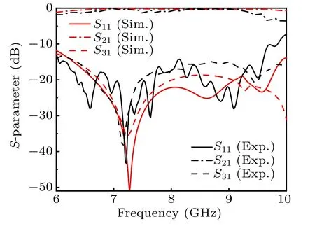
Fig.5. Comparision of S-parameter of plasmonic circulator obtained from the simulation(Sim.) and the measurement(Exp.).
4. Conclusions
In conclusion, we have proposed a three-port, and rotationally symmetric plasmonic circulator based on nonreciprocal mode coupling. The modes inside the circular are SSPPs, which can propagate along the ultra-thin metallic comb plasmonic waveguides. The non-reciprocal mode coupling is enabled by the ferrite which is a gyromagnetic material having a permeability tensor with both diagonal and offdiagonal terms. By meeting impedance matching condition,the proposed circulator can operate in a broad frequency band of 6.0 GHz-10.0 GHz with insertion loss less than 0.5 dB.Furthermore, an equivalent circuit model has been employed to get a quantitative understanding. The circulator has been also validated by building a prototype and the results from simulations, circuit model,and measurements show a good agreement.

- Chinese Physics B的其它文章
- Nonlocal advantage of quantum coherence in a dephasing channel with memory?
- New DDSCR structure with high holding voltage for robust ESD applications?
- Nonlinear photoncurrent in transition metal dichalcogenide with warping term under illuminating of light?
- Modeling and analysis of car-following behavior considering backward-looking effect?
- DFT study of solvation of Li+/Na+in fluoroethylene carbonate/vinylene carbonate/ethylene sulfite solvents for lithium/sodium-based battery?
- Multi-layer structures including zigzag sculptured thin films for corrosion protection of AISI 304 stainless steel?