
MSONoC: a non-blocking optical interconnection network for inter cluster communication①
2020-10-09 07:38:16JiangLinCuiPengfeiShanRuiWuHaoyue
High Technology Letters 2020年3期
Jiang Lin (蔣 林)②, Cui Pengfei , Shan Rui , Wu Haoyue
(*Integrated Circuit Laboratory, Xi’an University of Science and Technology, Xi’an 710054, P.R.China) (* *School of Electronic and Engineering, Xi’an University of Posts and Telecommunications, Xi’an 710121, P.R.China)
Abstract
Key words: network on chip (NoC), optical interconnection, wavelength division multiplexing (WDM), non-blocking, multilevel switching
0 Introduction
In order to improve overall performance of the system and enhance parallel efficiency of the algorithm, the number of processor cores integrated on a single chip is increasing. The chip area becomes larger and larger, which means that the communication delay between processor cores and memory become very large, so data communication becomes the bottleneck of the overall system performance. The network on chip (NoC)[1]architecture alleviates the communication delay between processor cores on-chip to some extent, but the number of processor cores increases. Optical network on-chip (ONoC) has the advantages of effective bandwidth, transmission delay and power consumption superior to traditional electrical interconnections, and plays an increasingly important role in the core communication of the chip[2].
In circuit switching interconnection network, active micro-ring resonator is mainly used to build optical router, and it is suitable for large-scale computation on chip. Many optical routers are designed by researchers. Refs[3-5] optimized the traditional optical router, reduced the number of micro-ring resonator, and designed a 4-port and 5-port optical router. For the extensibility of network, Ref.[6] designed a 6-port optical router. Ref.[7] used the crossing angles of 60 degrees or 120 degrees instead of the conventional 90 degrees crossing angle to reduce the crosstalk noise in the waveguide crossing regions. Ref.[8] utilized the feature of micro-ring resonator that the optical signal can be rotated 90 degrees and 270 degrees in the MR, and it designed a 5-port optical router by allocating the specific wavelengths for routing. The number of MRs is reduced further. A kind of network structure in one cluster is designed with the optimized 5-port optical router. Communication intra cluster[9,10]uses general electric interconnection network, and communication inter cluster uses optical interconnection network, so the communication delay can be reduced effectively. With the development of 3D technology, Ref.[11] optimized the traditional 5-port optical router based on crossbar and Ref.[12,13] designed a 7-port optical router. Although the number of micro-ring resonators decreases, the insertion loss becomes very small, the confliction of data communication in active optical interconnection networks are more worse, at the same time, making link utilization very low.
In packet switching interconnection network, WDM technology is used to allocate specific wavelengths to achieve point-to-point communication. Due to the limitation of wavelength, it is suitable for small-scale interconnection. Ref.[14] used several 2×2 optical switches to construct a λ-router and realize a full optical connection structure for multi-processors. Ref.[15] designed a 4×4 optical switch which consists of 8 MRs. Ref.[5] designed a 5×5 optical switch and Ref.[11] designed a 7×7 optical switch. By connecting the switch with the bending waveguide, the non-blocking parallel access is implemented, but the number of MRs is large, and the power consumption cannot be tolerated. A two-level switching interconnection network was designed by using passive broadband micro-ring resonator, but the second level switch structure adopted crossbar switch mode, and the micro ring redundancy was big[16,17]. Refs[18-20] based on interconnection structure in cluster, used two links to achieve intra cluster communication and inter cluster communication. Although the number of wavelengths can be reduced, the exchange structure on the boundary needs special design, which is not conducive to the expansion of network scale. Ref.[21] employed 8 broadband micro-ring resonators and implemented a 5-port optical router. Using WDM[22-24]technology, the router can exchange the signal in between the 5 ports without blocking. However, as the network size is increasing, the structure needs to be redesigned.
To alleviate above problems and adapt to the topology of the video array processor, a broadband micro-ring resonator is used in this paper to design a multi-level switching inter-cluster communication optical interconnection network called multilevel switching optical network on chip (MSONoC), enabling non-blocking concurrent access between multiple processing element clusters. The results show that compared to λ-route, GWOR, Crossbar, and the new topology structure, the number of micro-ring resonators of MSONoC is reduced by 95.5%, 95.5%, 87.5%, and 60%, respectively, while the insertion loss of MSONoC increase is quite small.
1 Optical interconnection network
1.1 Basic optical switch structure
Many micro-ring resonators are responsible for the coupling, transmission, steering and filtering of optical signals in an optical interconnect network. Micro-ring resonators are divided into active and passive by transmitting wavelength signals.
As shown in Fig.1, for the conventional micro-ring resonator, when the input signalλiis consistent with the resonant wavelengthλrof the micro-ring resonator, the signal will be rotated 90 degrees around the micro-ring resonator; when the wavelength of the input portλiand the resonant wavelengthλrare not isochronous, the signal will be output in the horizontal direction.
The broadband MR[25-27]plays an importand role in an active comb switch, it allows multiple wavelengths of light to be switched simultaneously. Similar to the traditional micro-ring resonator, its input optical signal can drop or through along the broadband micro-ring resonators (BMR), but once the BMR is configured, it can have multiple resonant wavelengths to transmit and forward a variety of wavelengths of optical signal.

Fig.1 Structure of traditional micro-ring resonator and multi resonant wavelength micro-ring resonator
1.2 The basic switch unit of MSONoC
Two crossed optical waveguides and one BMR form a 2×2 optical switch unit. Assuming that the resonant wavelength of the BMR is a set ofλr, if the input light wavelength belongs to the set ofλr, theI0signal is rotated 270 degrees around the BMR and output fromO0, and theI1signal is rotated 90 degrees around the BMR to the output ofO1; otherwise, theI0signal is output fromO1along the waveguide. TheI1signal is output fromO0along the waveguide.
It is usually point-to-point communication process of storage access in the multi-core system, so it is necessary to filter the specific wavelength signal of an input port.
By analyzing the optical signal exchange process of the basic 2×2 optical switch unit, it is found that the BMR actually filters the corresponding wavelengths from the optical signals of the 2 input ports respectively, and distinguishes the signal from the wavelength to the resonant wavelength setting. Signals with wavelengths do not belong to the resonant wavelength set, so a particular wavelength signal can be filtered from the input port by multiple exchanges.
Accordingly, in order to achieve multiple switching purposes, many similar optical switching structures are required. By using and distributing a 2×2 basic optical switch unit, as shown in Fig.2, the structure of the optical switch unit of 4×4, 8×8 and 16×16 can be easily obtained. Fig.3 shows the 16×16 optical interconnect switch structure.
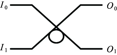
Fig.2 Structure diagram of basic 2×2 light switching unit

Fig.3 16 × 16 optical switching unit structure diagram
1.3 MSONoC architecture
As for a structure with node numberN,Nelectro-optical conversion units andNphotoelectric conversion units are required for sending and receiving the request signal. At the same time, log2Nlevel switches are required, and each stage of switch consists ofNbroadband micro-ring resonators. Among them,Nmust be a value of power of 2. This paper takes the structure with the node of 16 as an example.
As shown in Fig.4, the 16×16 optical interconnection network requires a 4-stage optical switch to transmit a request signal during the memory access process. The first level of switching consists of 16 port switching units, and the second level of switching consists of two 8-port switching units. The third stage switch consists of four 4-port switch units, and the fourth stage switch consists of eight dual port switch units.
The 16-port switching unit of the first-stage switching switch is composed of 16 micro-ring resonators and 16 optical waveguides, and the resonant wavelength of each micro-ring resonator isλ0,λ1,λ2,λ3,λ4,λ5,λ6,λ7, performing first-stage switching; second-stage switching switch, each micro-ring resonator resonant wavelength isλ0,λ1,λ2,λ3,λ8,λ9,λ10,λ11; third-stage switching switch, each micro-ring resonator resonant wavelengths isλ0,λ1,λ4,λ5,λ8,λ9,λ12,λ13; fourth-stage switching switch, each of the micro-ring resonator resonance wavelengths isλ0,λ2,λ4,λ6,λ8,λ10,λ12,λ14.
2 Communication process
For a wavelength assignment method is designed for the proposed ONoC system. A specific carrier wavelength is assigned for each communication pair. ForNnodes architecture, Table 1 and Table 2 show the wavelength assignment of 8×8 and 16×16 optical networks respectively. Table 3 is the algorithm for wavelength assignment.
Table 1 and Table 2 are 8×8 and 16×16 optical interconnect network wavelength allocation. The different size of optical interconnect networks on chip uses different wavelengths, between processing units ensure non-blocking transmission. When the signal is transmitted, the waiting time is smaller. Therefore, the problem of blocking and delay should be fully considered when configuring the resonant wavelength of each micro-ring resonator to realize large-scale processing of non-blocking communication between cells.
Before the request is issued, the response configuration packet information needs to be transmitted at the electrical configuration layer, and the BMR in the optical transport network is configured according to the requirements of each resonant wavelength. When the configuration is completed, each processing element issues a storage access request signal through the electro-optical conversion device, the request signal is coupled to the corresponding wavelength, and the non-blocking parallel access can be completed through the MSONoC structure.

Fig.4 Optical link layer structure

Table 1 Wavelength assignment scheme in 8×8 optical interconnection network
To more clearly describe the concentric process, the micro-ring resonators in the MSONoC structure are numbered. The thick density dashed line and fine density dashed lines in Fig.5 indicate the case where PEG4 and PEG2 simultaneously access the RAM 7. When PEG4 needs to access the memory RAM 7, according to the wavelength allocation table, the required wavelength is λ1. When the request signal reaches the MR5, since the wavelength λ1is within the resonant wavelength group of the MR8, it rotates along the micro-ring; the MR9, λ1of the secondary switch structure also belongs to the resonant wavelength group of the MR9, and then rotates along the micro-ring; enters the micro-ring of the third-stage switching structure, λ1belongs to the resonant wavelength group of the MR20, and will enter the MR28 of the fourth stage switching structure, λ1does not belong to the resonant wavelength set of the MR28, which propagates along a straight line and reaches the corresponding memory.

Fig.5 Signal transmission path
Analyzing the access process of PEG4 and PEG2 to RAM 7, the MSONoC structure can implement non-blocking parallel access of one or more memories of multiple processing meta-clusters, but memory can only responds to one request at the same time. In this case,each bank requires a request cache unit to buffer the request signal that has not yet responded when multiple processing element clusters are simultaneously accessed.
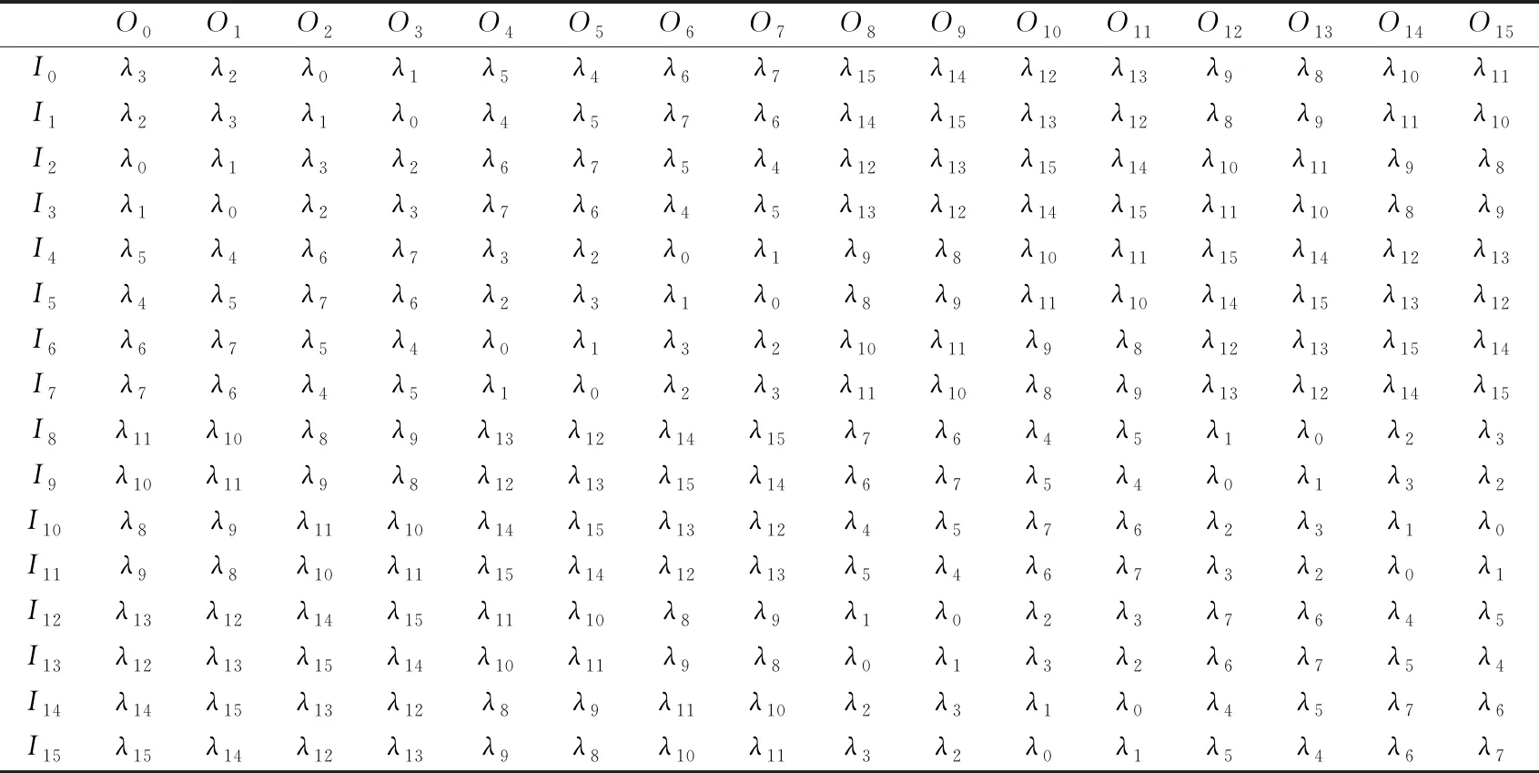
Table 2 Wavelength assignment scheme in 16×16 optical interconnection network

Table 3 The algorithm of optical router design
3 Network performance analysis
Waveguide, wavelength and micro-ring resonators are 3 important parameters in an optical interconnect network on chip. The number of micro-ring resonators and waveguides affects the insertion loss of the entire network. Therefore, to improve the performance of the optical interconnection network, it is necessary to use the minimum number of micro-ring resonators and waveguides under the premise of ensuring the basic functions of the optical interconnection network. As the scale of optical interconnection network becomes larger, to ensure non-blocking communication of large-scale optical interconnection networks, the wavelengths used in the networks play a vital role. This paper uses wavelength division multiplexing technology to synthesize and decompose optical wavelengths, setting different fixed wavelength ranges for different micro-ring resonator resonances. The wavelength assignment tables in Table 1 and Table 2 are used to achieve non-blocking signal transmission. In optical interconnect networks on chip, the loss and dispersion of the optical waveguides that make up the micro-ring are not considered in this paper. Therefore, different input wavelengths have little effect on the network from the aspects of waveguide loss and dispersion.
The number of micro-ring resonators in the optical interconnect network, the number of wavelengths used in the network, and the insertion loss are closely related to the performance of the entire network. The insertion loss can be calculated by Eq.(1).
IL=∑ILbend+∑ILcross+∑ILdrop+∑ILthrough
(1)
where,ILis the insertion loss,ILbendis the waveguide bending loss,ILcrossis the waveguide direct loss,ILdropis the micro-ring resonator resonant loss, andILthroughis the micro-ring resonator direct loss. According to Ref.[3], the parameters in the formula are shown in Table 4.

Table 4 Optical signal parameters
Table 5 presents the statistical results of the number of micro-ring resonators and the number of wavelengths on the 2×2, 4×4, 8×8, and 16×16 network sizes. It can be seen from the table that with the network scale expansion, the number of micro-ring resonators and the number of wavelengths increases. As the size of the optical network increases, the number and size of wavelengths required are matched.
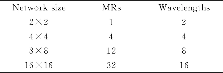
Table 5 Results of resource statistics under
Table 6 shows the wavelength range of each stage of the optical switching unit. In the wavelength range of λ0-λ15, the obtained values are 1553.33 nm, 1552.52 nm, 1551.72 nm,1550.92 nm,1550.12 nm,1549.32 nm,1548.52 nm,1547.72 nm,1546.92 nm,1546.12 nm,1545.32 nm,1544.53 nm,1543.73 nm,1542.94 nm, 1542.14 nm, and 1541.35 nm, respectively. Therefore, the reasonable allocation of wavelengths for large-scale optical networks, the structure designed in this paper can meet the non-blocking communication between processing elements.
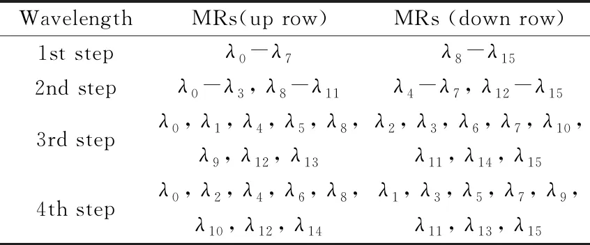
Table 6 Wavelength range assignment
Fig.6, Fig.7, and Table 5 display the comparison results of the number of micro-ring resonators and the number of wavelengths for the structure of MSONoC and the λ-router[14], GWOR[15], Crossbar[28], and new topology[16]structures respectively. The results show that the MSONoC structure has a great advantage in the number of micro-ring resonators, which makes the insertion loss small, and the number of wavelengths required is not much different from the reference structure.

Fig.6 Comparison of the number of microring resonators

Fig.7 Comparison of wavelengths in different structures
In order to facilitate comparison, based on the design of the original 16×16 scale, this paper carried out the design of an 8×8 scale multilevel switched optical interconnect network structure. Table 7 shows the different structures of the 8×8 network scale of insert loss comparison results.
With the analysis of the above results, under the condition that the insertion loss does not increase much, the design of this paper reduces the number of micro-rings by 95.5%, 95.5%, 87.5% and 60% compared to the λ-route, GWOR, Crossbar, and new topology structures on the 16×16 network size. Compared with the traditional electrical interconnection, the optical interconnection network uses the wavelength division multiplexing technology to make the wavelength distribution reasonably realize the non-blocking communication between the multi-cores, which has great advantages for the current large-scale circuit popularization.
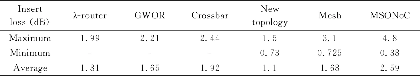
Table 7 Insertion loss comparison results in different structures
4 Conclusion
In this article, multi-wavelength resonant micro-ring resonators are used to design multi-stage switching optical interconnection networks to enable non-blocking parallel access to cluster memory of multiple processing elements. At present, with the popularity of large-scale circuits, the performance requirements of the entire circuit for inter-processor communication are becoming stricter. The optical interconnect network designed in this paper can realize large-scale circuit non-blocking communication, and the number of micro-ring resonators is much smaller compared with the state of the art optical network structure. The results show that compared with λ-route, GWOR, Crossbar and new topology structure, the number of micro-ring resonators of MSONoC is reduced by 95.5%, 95.5%, 87.5% and 60%, respectively, and the minimum link insertion loss is 47.9% and 47.5% lower than the new topology and mesh structure. Therefore, compared with new topology and mesh structure, MSONoC structure has a certain advantage.
 High Technology Letters2020年3期
- High Technology Letters的其它文章
- Image texture smoothing method by a novel L0-norm optimization model①
- Health status assessment of axial piston pump under variable speed①
- Comparison of availability and reliability among differentcombined-GNSS/RNSS precise point positioning①
- Design of a DSLM-based cerebral palsy action rehabilitation training system①
- Mobility matrix of a weakly coupled parallel multi-DIM isolator based on axial force solution①
- Detecting and adaptive responding mechanism for mobile WSN①