
Innovation and Application of Key Technologies of Arc Spring Damping Flywheel Assembly
2019-12-26 03:17:58HanTianyuHuJiangping
中阿科技論壇(中英文) 2019年4期
Han Tianyu,Hu Jiangping
(1.Nanjing University of Aeronautics and Astronautics,Nanjing,Jiangsu 210001;2.Hubei Tri-Ring Clutch Co.,LTD,Huangshi,Hubei 435000)
Abstract:With the application of CVT and DCT technology,the traditional clutch assembly cannot meet the increasing higher requirements of vibration and noise reduction.The innovative design of arc spring damping flywheel assembly adopts compact and lightweight integrated structure,large torsional angle and low stiffness arc spring damping,independent damping system of pre-vibration reduction,laser welding and other technologies.It solves the technical problems related to the production process in the process of technology application,and can effectively reduce vibration and noise.
Key words:arc;spring;damping;flywheel;assembly
I.Project Context
With the application of CVT (continuous variable transmission)and DCT (dual clutch transmission)technology,the traditional clutch assembly cannot meet the increasing higher requirements of vibration and noise reduction.The flywheel vibration reduction technology which can effectively reduce vibration and noise arises at the historic moment,but it is still blank in China.In order to break through foreign technology monopoly,create independent core technology,realize domestic instead of imported,timely meet the market demand of domestic CVT continuous variable transmission and DCT dual clutch transmission model,Hubei Tri-Ring Clutch Co.,Ltd developed arc spring damping flywheel assembly project[1].
The key technical problems to be solved for arc spring damping flywheel assembly are as follows:(1)Compact and lightweight design;(2)Design and production process of arc spring structure dimension;(3)Selection and sealing of grease;(4)Welding reliability between cover plate and main flywheel body;(5)Machining precision of thin-walled parts.

Figure 1 Structure Chart of Arc Spring Damping Flywheel Assembly

Figure 2 Real Product Picture of Arc Spring Damping Flywheel Assembly

Figure 3 Assembly View of Traditional Clutch Assembly and Single Mass Flywheel Assembly
Combined with the development trend of foreign flywheel vibration reduction technology and the demand of domestic market,the arc spring damping flywheel assembly technology is formed by carrying out research around the above key technical issues.The general idea is as follows:(1)the compact lightweight integrated structure technology is proposed to integrate the traditional clutch vibration reduction system with the single mass flywheel structure design,break through the limitation of space layout,and realize the compact lightweight design;(2)the arc spring with large torsion angle and low stiffness is proposed to reduce vibration,adopt arc structure instead of cylindrical structure to realize the design of large angle and low stiffness of damping spring;(3)the pre-damping technology of independent damping system id proposed to realize two-stage damping;(4)the laser welding technology is put forward to solve the welding reliability and ensure the airtightness;(5)through the test verification of different grease,determine the type of grease that meets the requirements,and solve the problem of high temperature wear of arc spring.The arc damping flywheel assembly constructed by the above mentioned technology has reached the international advanced level of similar products in terms of the main technical indexes[2].
The arc spring damping flywheel assembly is mainly composed of quality loop,launching gear rotational,active flywheel assembly,chute,arc spring,flange,driven flywheel assembly,cover plate,grease and other parts.The overall structure is shown in figure 1,and the actual product is shown in figure 2.
II.Key Technology
(i)Compact lightweight integrated structural technology.The traditional clutch damping system is integrated with the single mass flywheel to save axial space and reduce the weight of the flywheel vibration absorber.
Aiming at the limitation of space layout and heavy weight of single mass flywheel and traditional clutch (as shown in figure 3),this paper proposes compact lightweight integrated structure technology,break through the limitation of the space layout of the traditional clutch damper,design and integrate the traditional clutch damping system with the single mass flywheel[3].
The flywheel assembly of the new structure technology (as shown in figure 4)not only contains the functions of transmission,torsion and vibration reduction of the single mass flywheel and the traditional clutch,but also carries out lightweight treatment on the premise of guaranteeing the quality of the product,which makes the space layout more compact and saves the axial space.For example,the motorcycle type with the engine torque of 210Nm(1.5T),the weight of the traditional flywheel and clutch is about 13kg,while the new arc spring vibration reducing flywheel weight is about 10kg,which reduces the weight by 23%.
(ii)Large torsion angle and low stiffness arc spring damping technology.In the part of flywheel and connecting transmission,vibration damping design is adopted to attenuate the irregular torsional vibration of the engine through the arc-shaped spring vibration damping system,the effect of vibration reduction is remarkable.
The traditional clutch assembly and its damping spring structure (as shown in figure 5 and figure 6),the damping spring is a cylindrical spring.The spring material is generally 55CrSI,allowable stress does not exceed 850MPa.The free length of the spring is generally 20~45 mm according to the design of the spring cavity.The torsion angle of this cylindrical spring is small (as shown in figure 7),generally in the 15°~25°,and the damping effect is not obvious.
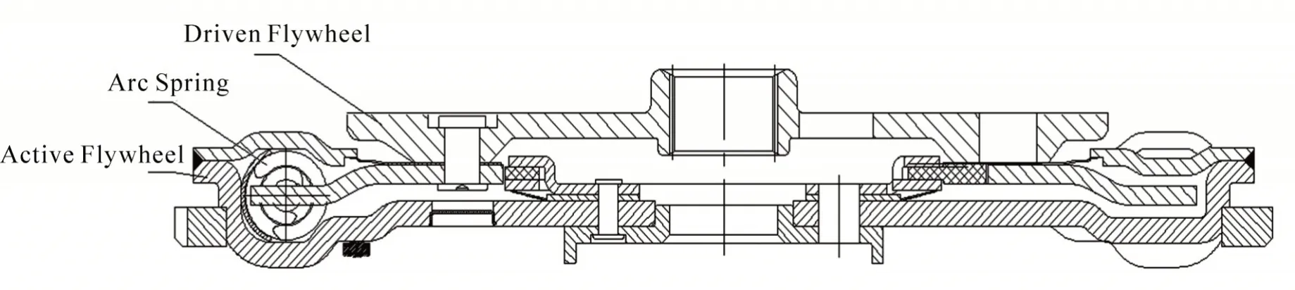
Figure 4 Assembly View of Arc Spring Damping Flywheel Assembly
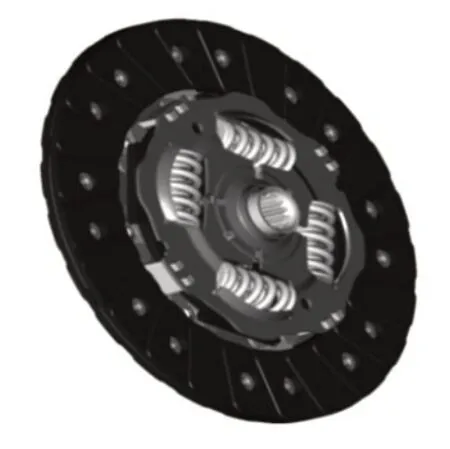
Figure 5 Assembly Drawing of Traditional Clutch

Figure 6 Structure Diagram of Traditional Clutch Assembly Vibration Reduction Spring
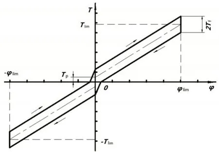
Figure 7 Vibration Reduction Curve of Traditional Clutch Assembly

Figure 8 Assembly Drawing of Arc Spring Vibration Reducing Flywheel

Figure 9 Structure Drawing of Arc Spring

Figure 10 Graph of Arc Spring Damping Flywheel Assembly Damping

Figure 11 The Inside of the Circle is The Structure Diagram of Independent Damping System

Figure 12 Enlarged Schematic Diagram of Independently Damping System Structure
Arc spring damping flywheel assembly arc spring structure (as shown in figure 8 and figure 9),the spring is shaped with arc,and fits the active flywheel cavity.The spring material is generally SWOSC-V,allowable stress does not exceed 1000 MPa,this material has higher strength and better reliability.The free angle of the arc spring is 156°~162°,and the torsion angle is relatively large (as shown in figure 10).Generally,it can reach 50°~70°.When delivering the same torque,because the arc damping flywheel has a higher torsion angle and lower stiffness,it has more significant damping effect[4].
(iii)Independent damping system pre-damping technology.Through the design of independent damping system,as well as the improvement of spring material and manufacturing process,the vibration amplitude of the engine during idle operation can be effectively reduced to improve the NVH comfort of the vehicle.
In order to ensure a better vibration isolation effect in the arc spring damping flywheel assembly,an independent damping system is added to the entire damping range of the flywheel assembly (as shown in figure 11).The independent damping system is mainly composed of washer,damping plate,stop damping plate and disc spring(as shown in figure 12).The washer and stop damping plate are made of SPHE steel,the damping plate is made of PA66 nylon,and the disc spring is made of 65Mn.The function of the disc spring is to provide a stable axial pressure,which acts on the stop damping plate,causing the stop damping plate and the washer to compress the damping plate together;the damping plate is meshed with the flange.When the flange rotates relative to the active flywheel,it will drive the damping plate to rotate together;The washer and the stop damping plate are riveted to the active flywheel.When the damping plate rotates,it will move relative to the washer and the stop damping plate and generate friction,which is called damping[5].
Figure 13 is the curve diagram of vibration reduction characteristic of arc damping flywheel assembly,in the process of torsion detection,the back and forth compression arc spring forms the travel stroke and return stroke in the curve,and the difference between the travel stroke and return stroke is the damping.The damping is mainly caused by the friction between the damping plate and the washer and the stop damping plate in the damping system.

Figure 13 Curve Diagram of Vibration Reduction Characteristic of Arc Damping Flywheel Assembly
Damping is related to friction area,friction coefficient and axial pressure of two parts in the friction pair,and these three factors can be quantified and controlled in the design of parts,so as to ensure the stability and reliability of the damping system,then effectively reduce the vibration amplitude of the engine during idle operation and improve the NVH comfort of the vehicle.

Figure 14 Diagram of Welding Position
(iv)Laser welding technology.Laser welding technology is adopted in the arc damping flywheel assembly shock absorber to effectively solve the sealing problem between the cover plate and the main flywheel body[6].
In order to ensure the reliability and tightness of the welding between the active flywheel and the cover plate (as shown in figure 14),the original argon arc welding is adjusted to laser welding.

Figure 15 Schematic Diagram of Local Argon Arc Welding

Figure 16 Diagram of Argon Arc Welding Crack

Figure 17 Partial Schematic Diagram of Laser Welding
The original argon arc welding surface temperature is above 4000 °C,the time cycle is 120 seconds/piece,and the welding speed is slow,resulting in the parts being in high temperature for a long time,causing large deformation and affecting the product quality.The welding effect is shown in figure 15.At the same time,affected by the bevel angle of the parts in the welding process,the welding solution could not fuse with the base material,forming a virtual welding,which would crack during the vehicle operation and cause quality accidents (as shown in figure 16).
The surface temperature of laser welding is between 3000 °C and 4000 °C,and the time cycle is 30 seconds/piece.The welding speed is fast,the cooling speed of the parts is fast,the heat affected area is small,and the deformation of the parts in the welding process is small.The welding effect is shown in figure 17.At the same time,there are no other elements added in the welding process,and only the two welding base metal form a whole after melting,with high strength.At present,the welding depth of laser welding can generally reach to 3.5~4.0 mm (as shown in figure 18),which fully meets the reliability requirements of flywheel operation.
III.Compared with the main parameters,effects and market competitiveness of similar technologies at home and abroad

Figure 18 Schematic Diagram of Penetration Depth in Cutting Laser Welding
(i)The 230 specification flywheel vibration absorber developed by the above-mentioned arc spring vibration reducing flywheel assembly technology (as shown in figure 2),the testing by Hubei provincial motor vehicle and parts quality supervision and inspection station showed that the main performance parameters have reached the international quality level of congeneric products.Specific comparison data are shown in table 1.
(ii)Comparison of Damping Effect between Arc Spring Flywheel Assembly and Traditional Clutch Assembly
Figure 19 is the NVH test of the traditional clutch in the 3-gear WOT condition,the maximum axial angular acceleration of the gearbox input is 1887.6rad/s2 after damping through the clutch,in the engine area of 2000rpm~3500rpm,the interval shock rate reaches up to 40%[7].
Figure 20 is the NVH test of the arc spring damping flywheel assembly under the WOT working condition of level 3.The maximum axial angular acceleration of the gearbox input was 392.4rad/s2 after vibration reduction by the arc spring,and the maximum interval vibration rate was 81% in the engine area of 800 rpm~4500 rpm.
(iii)Comparison of Market Competitiveness.The arc spring damping flywheel assembly project fills the domestic gap,its main technology has reached the international advanced level of similar products and realized import substitution.In the re-cent years,a large number of installation use has been carried out in Chongqing Yu’an Huaihai Power Co.,Ltd and other units and has achieved good economic and social benefits,the market prospects are broad[8].
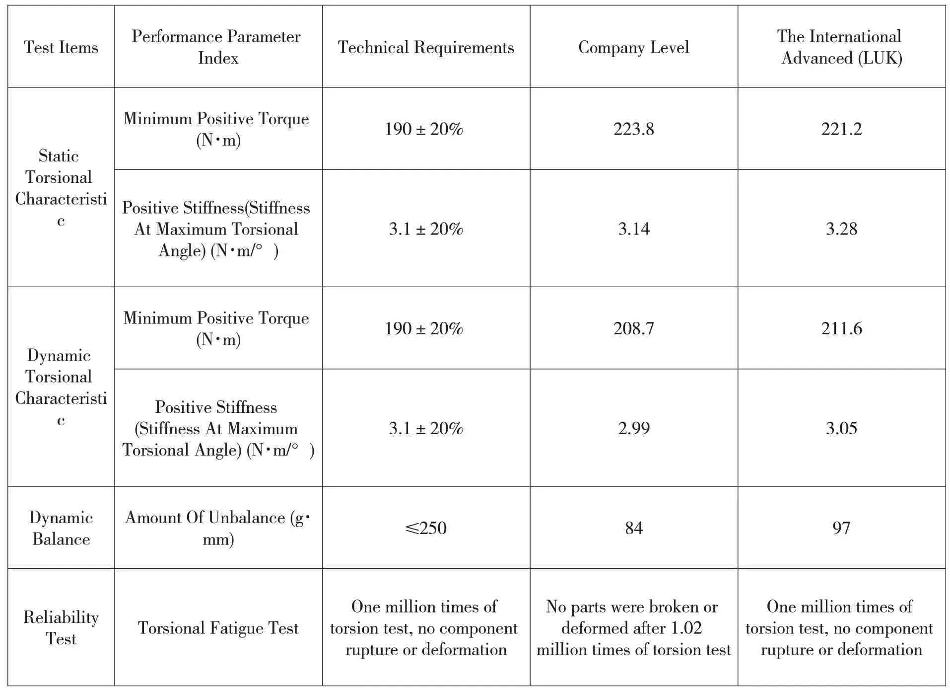
Table 1 the Correlation Data of Main Parameters of the Current Foreign Similar Technology
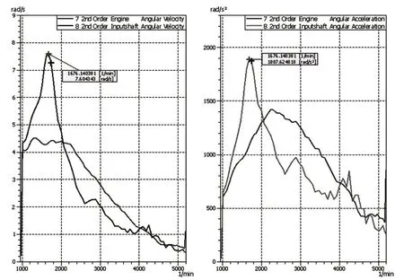
Figure 19 NVH Test Curve of Traditional Clutch in 3-Gear WOT Condition

Figure 20 NVH Test Curve of Arc Spring Damping Flywheel Assembly in 3-Gear WOT Condition
IV.Conclusion
The arc spring damping flywheel assembly technology series of products can basically meet the demand of most models on the market,the loading effect is good,but the adaptability of this technology still needs to be improved in the application of some vehicles with higher requirements on damping.For example,in the application environment of the Getrak 7DCT300 transmission,due to the lightweight design of this transmission,the gears of each gear position are light in weight and small in inertia,resulting in the whole transmission is very sensitive to the vibration transmitted from the engine end.The angular acceleration of this gearbox after damping through the arc spring flywheel is required to be less than 250rad/s2,otherwise the gearbox gear will be hit.However,the existing arc spring damping flywheel assembly technology can only achieve angular acceleration less than 400rad/s2.At present,the only product that can really solve this problem is the dual mass flywheel with eccentric pendulum structure,which is still under development.
With the rapid development of automobile industry,especially the extensive application of CVT and DCT transmission technology in China,higher requirements for vibration and noise reduction(NVH)will be put forward.In order to meet these new requirements in the market,the research on dual mass flywheel with eccentric pendulum structure based on arc spring damping flywheel assembly technology and dual mass flywheel technology with torque protection and other structures will be the company's future research and development direction.

- 中阿科技論壇(中英文)的其它文章
- Study on the Casas-Alvero Conjecture of Univariate Polynomials
- Application of Computer Lingo Software in Production Efficiency
- Maple Demonstration Example of Spatial Graphic
- Design of Tractor Traction Resistance Monitoring System for Potato Harvest Equipment
- Study on Gemological Characteristics of Changbai Jade
- Research on Medical Image Segmentation Based on Morphology