
A Revised Method for Predicting Added Waves Resistance Based on Comparison of Theoretical and Empirical Results for VLCC Hull Forms
2019-01-09 08:26:42YANGChunleiZHURenchuanFANTaoZHOUWenjunMIAOGuoping
船舶力學(xué) 2018年12期
YANG Chun-lei,ZHU Ren-chuan,FAN Tao,ZHOU Wen-jun,MIAO Guo-ping
(1.Jiangnan Institute of Technology,Jiangnan Shipyard(Group)Co.,Ltd.,Shanghai 201913,China;2.State Key Laboratory of Ocean Engineering,School of Naval Architecture,Ocean and Civil Engineering,Shanghai Jiao Tong University,Shanghai 200240,China;3.Collaborative Innovation Center for Advanced Ship and Deep-Sea Exploration,Shanghai 200240,China)
Abstract:A practical method for engineering prediction is presented based on investigation on comparison of results obtained from a modern theory method and empirical formulas.Due to the hypothesis and predigesting,theoretical methods could not make good accurate prediction for added resistance due to short waves,and empirical formulas are limited to special hull forms.VLCC ships at constant speed in head waves are calculated and analyzed comparably,and the effects of draft and speed are taken into account.A 3-D panel method based on the Green function of translating and pulsating source on the horizontal line segments is used to solve potential theory.Added resistance due to the radiation is obtained by 3D radiation energy method,and that due to the diffraction is obtained by the second order steady-state force equation.STAWAVE2 method recommended by ISO15016-2015 is adopted as the semi-empirical method.The applicability of the present methods is discussed on the basis of analysis of the added resistance due to radiation and diffraction.The revised semi-empirical method is derived after numerical calculations are conducted.Finally,the revised formulas which reflect the characteristics of geosim hull forms are presented.
Key words:added resistance due to radiation;added resistance due to the diffraction;radiation energy method;Green’s function;STAWAVE2
0 Introduction
Due to the more stringent requirements of safety enhancement and emissions reduction,prediction of the added wave resistance of ships is getting more and more important.An assessment procedure for minimum power is provided in MEPC(Marine Environment Protection Committee)232(65)resolution,in order to maintain maneuverability in adverse conditions for ships,complying with EEDI(Energy Efficiency Design Index)regulation.The evaluation of EEDI has been enforced since 1 January 2013 in MEPC 232(65)resolution,regarding the Green House Gas emission of the navigation of ships.The effective consideration to improve EEDI index is achieved by reducing speed,but that will result in unconformity to the minimum power requirement which is calculated by minimum power lines,especially for large-scale ships.In such cases more accurate method for predicting the added resistance should be used.Conservative formulas for the added resistance are not applicable for the sophisticated consideration of requirements of two resolutions mentioned above.Moreover,the accuracy of the added resistance is key to final EEDI report,which is obtained from correction data of sea trials based on ISO-15016:2015[1].Model tests can be conducted for the most reliable prediction when circumstances permit,but factors of cost and time preclude such tests.Therefore the investigation and validation on empirical and numerical methods are getting more and more important.
Procedures recommended[2]for calculating added wave resistance by ITTC are adopted by ISO.The procedures include empirical methods from the STA-JIP(Sea Trial Analysis Joint Industry Project),namely STAWAVE1 and STAWAVE2,and the semi-theoretical method of the NMRI(National Maritime Research Institute).However,these methods are applicable to some extent to the ship type,draft,wave frequency and other factors.The Specialist Committee on Performance of Ships in Service(PSS Committee)[3]selected foregoing three methods and six type of ships to have comparison study for added resistance,and understand which method was the best method for the correction of speed/power trial.The results show that NMRI method combined with tank model in short waves gives the considerable accuracy.Returning to the reanalysis,the STAWAVE2 method would be convenient and preferred at the early design stage in the range of intermediate and short wave for the fine hull lines,because the empirical formulas for the diffraction resistance are relatively rational.NMRI(National Maritime Research Insititute)method has a better theoretical basis for the radiation resistance,and is more reasonably comprehensive for the diffraction resistance because of accommodation of correction of speed effect and waterline of the hull.NMRI method recommended by PSS,although better than most others,lacks transparency and universalization in numerical method of 3D potential in the flow field and Kochin function.Note worthily,prediction of the added resistance in short waves at about λ/Lpp=0.3 relies on empirical parameters for the speed and draft effect whatever employing theoretical or empirical method.For a specialist ship,practical predictions are based on the in-house data relating to a similar basis ship.The difficulty of the accumulation of data is how to correct by the way of synergetic re-analyses of modern and older methods.
At the framework of linear potential flow theory,two methods are available to estimate the added resistance:the far-field and near-field methods.The far field method was firstly introduced by Maruo[4]and derived the equation of steady second order force obtained by calculating the change of momentum for radiated wave energy.Joosen[5]revised the added resistance method based on Maruo method,and NMRI adopted the method for added resistance due to ship motions.Maruo method gives considerably accuracy for the cruiser stern ships,and does not apply the hull forms with bulbous bow.Joosen’s method improved the accuracy for the results of transom stern ships,but does not apply cruiser stern ships.Gerritsma[6]introduced the radiation energy method which is based on the far field method.Salvensen(1978)[7]investigated added resistance by calculating second order terms of disturbing forces and moments.Str?m[8]evaluated these methods and gave the conclusion that the prediction of added resistance lied in the range of ship forms and speed.Faltinsen(1980)calculated added resistance by integrating pressure on average wetted surface of ship hull based on near field method with good validation results.It is important to note that the value of added resistance is a second order term,and the accurate prediction suits the exact solution of the motion response,which requires accurate solution of the velocity potential.
Even though there is still controversy for the versatility and accuracy of the empirical approach of the ITTC,the method international organization is willing to promote such methods to improve due to the convenient and transparent calculation.For the practical prediction for the designers,the correction empirical formulas are established from tank tests data and theoretical results.Jinkine[9]developed an estimation formula of added resistance including the principle dimension of ships for the long wave length,however the value for the short wave length should be corrected.Havelock[10]derived the steady drag formula for the fixed vertical cylinders.Fujii[11]established semi-empirical formulas for the diffraction resistance based on Havelock.Kuroda[12-13]further corrected the Fujii formula.MARIN[14]calculated the added resistance due to diffraction and radiation relating to Jinkine method,and formed a basis for STAVWAVE2 method.Though the empirical formulas give considerable accuracy,estimation based on in-house database is important.
In this paper,based on the existing data of the basis ships in Jiangnan shipyard,the theoretical and the empirical methods are investigated in order to establish the improved model for predicting the added resistance with better accuracy and reliability for the VLCC type ship.A 3-D panel method based on the horizontal line segment translating and pulsating source panel is used to solve potential problem,and added resistance due to the radiation is obtained by 3D radiation energy method for ships,while one due to the diffraction is obtained by the second order steady-state force formula.STAWAVE2 method is adopted as the semi-empirical method.Comparable study is conducted and advantage of different methods is analyzed.Revised formulas reflecting the characteristic of VLCC are validated with good agreement with experimental data.
1 Theories of potential flow and added resistance
1.1 Potential flow theory
A right-handed orthogonal coordinate system fixed in the mean position of the ship with the x-axis in the direction of constant forward speed,and the z-axis vertically upwards through the center of ship gravity is considered.The ship is advancing at a constant mean forward speed U0in sinusoidal regular waves with an arbitrary heading.
Assuming the fluid is ideal,fluid motions are irrotational and potential flow theory can be applied to describe the wave.The total spatial velocity potential is decomposed:

where φ0is the incident wave potential,φ7is the diffraction potential of the fixed ship,ωeis encounter frequency,φjis the normalized velocity potential due to radiated motions in six degrees of freedom,is the complex amplitude of the j-th degree of freedom.φ0is given by:

where A is amplitude of the incident wave,ω0is circular frequency,k is wave number,H is the water depth,β is the incident wave angle.
For diffraction and radiation wave potential,the boundary value problem to be solved is:
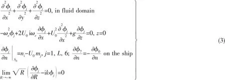
where U0is the ship speed,mjis the m-term,which represents the interaction between the steady forward motion and the periodic oscillatory motion of ships.By assuming that the steady potential is small,a simplified m-term can be written as:(m1,m2,m3)=(0,0,0 )and(m4,m5,m6)=(0,U0n3,-U0n2).
To solve the boundary value problem,the mixed source and dipole distribution model[15]and 3D translating&pulsating source Green’s function(3DTP)are used.And the boundary integral equation can be written as:
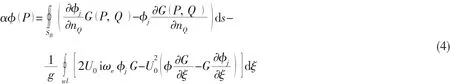
where α is solid angle of field point,P( x,y, z )is field point,Q( ξ,η, ζ)is source point,SBis average wetted surface of ship hull,wl is waterline.The Green’s function is expressed[16-17]by:

For the treatment of integration on the panel ΔSj,a more effective integration of horizon-tal line segment is used,as Fig.1 shown.The panel integration of the G*(P, )Q and its differential is converted into line integration:
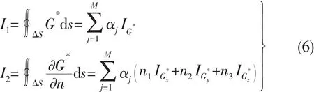
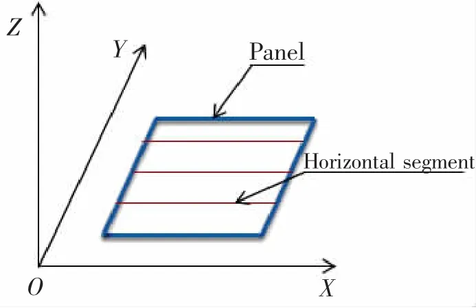
Fig.1 Discretization of a panel
where M is the number of horizontal line segments,αjis the weight coefficient of the j-th segment which is decided by the integral method used in vertical direction.The line segment integrationthe differentialandare expressed analytically shown in Ref.[16].Fig.2 shows hull lines and panel grids of KVLCC.
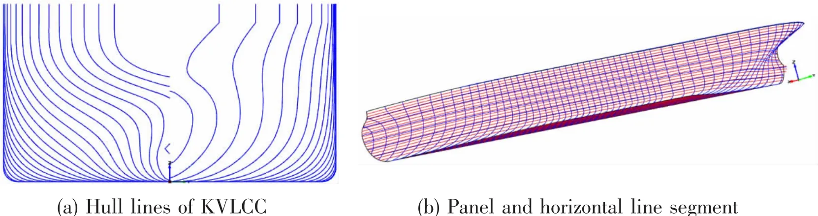
Fig.2 Hull lines and panel grids of KVLCC
Radiation and diffraction potential could be obtained by carrying out calculations for boundary element method(BEM).With φjknown,hydrodynamic coefficient such as added mass μjkand damping λjkcan be obtained.Wave forces including incident force)and diffraction force)are calculated separately by using respective potential φ0and φ7.Corresponding equation for motions can be given as
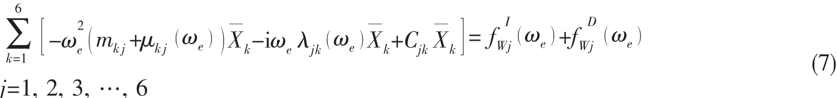
where mkjis inertia matrix,and Cjkis hydrostatic restoring terms.
1.2 Added resistance due to radiation
In principle of energy conservation,the radiation energy of an encounter period delivered by the ship should equal to the work done by average added resistance acting on ship hull.Radiation energy method of 3D BEM can be derived with reference of that based on strip method.This added resistance can be expressed as a function of hydrodynamic coefficient:

When the speed is zero,Ajk=Akj,the first term in the parentheses should be taken as zero.Then

where XkRand XkIare real part and imagine part of the complex amplitude of ship motion in k-th degree of freedom.The above equation is consistent with the Joosen method[5]for the zero speed ship.
1.3 Added resistance due to diffraction
It is assumed for ships that the disturbance potential is small compared to the incident potential (φBpp φ0),and therefore the second-order force of steady state derived based on Salvensen[7]can be expressed by:


2 STAWAVE2 method
2.1 Estimation for added resistance due to radiation
STAWAVE2 method is based on Jinkine method[9],and an approximate formula of nondimensional coefficient of added resistance due to radiation is as follows:

Then the added resistance is:

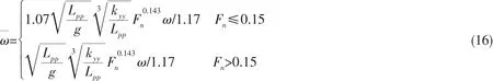
where a1=60.3and a2=Fn1.5exp(-3 .5Fn)account for the effects of the speed and principal dimensions for the peak value of radiation resistance.andresponse to inclination of the curve for the added resistance.Lpp,B,kyyand ζ are ship length,breadth,radius of gyration in lateral direction and wave amplitude,respectively.ω/1.17 is non-dimensional frequency,when=1,the added resistance is a minimum value.,and Cbis block coefficient.
After the verification of practical calculations,it is found that the peak of added resistance moves to the area of longer wave with a higher varying speed.
2.2 Estimation for added resistance due to diffraction
A semi-empirical formula based on Takahashi method[19-20]for calculating the diffraction added resistance is adopted,and the non-dimensional coefficient is:

Added resistance due to diffraction is:

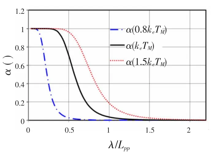
Fig.3 Comparison of the effects of draft and wave length
3 Comparisons of theory and empirical formulas
The different methods are used to validate two tankers,one is KVLCC2 which is a standard ship model for CFD validation,and another is a VLCC which is a built hull.The accuracy and applicable range will be analyzed by comparing tank test data and computed results.Main dimensions are presented in Tab.1.
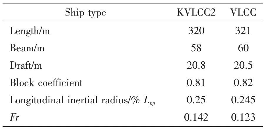
Tab.1 Main dimension of ships
3.1 Added resistance analysis
The heave and pitch motions are shown in Fig.4(a)and(b)based on 3D frequency domain method.The motion response results are in good agreement with experiment data.
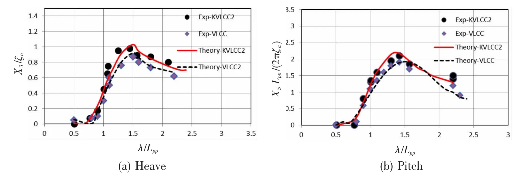
Fig.4 RAO
The results of added resistance at the speed of Fn=0.142 for KVLCC2 are shown in Fig.5,and the experimental data is from NTUA and INSEAN.Based on the analysis of theoretical and numerical calculation and comparisons with test data,it is concluded that:(1)As shown in Fig.5(a)the theoretical results of Rawin the range of λ/Lpp>0.7 and the resonance frequency range are in good agreement with experimental data,but the added resistance due to short wave is inaccurate;the empirical formulas enable a reasonably accurate prediction for Rawin the range of λ/Lpp<0.5,but resonance frequency range is not given a reasonable estimation.(2)As shown in Fig.5(b)the range of the maximum resistance obtained by SATWAVE2 method is in the lower frequency range;the added resistances in the range of λ/Lpp<0.5 for theory and STAWAVE2 are 25%-30%less than experimental data.The advantage of 3D translating and pulsating source method is that free surface condition is satisfied automatically and the dispersed error can be reduced.However,the viscous and nonlinear effects are great and not captured by potential flow theory,especially for full hull forms,moreover the major component at short-wavelengths is the diffraction resistance.Though the panel density is increased to improve the numerical accuracy,it is very difficult to accurately predict in short wavelength range.
For the VLCC,the relative wave length is short in the condition of the actual sea trial and service operation.The foregoing results show that the theoretical method has a limitation and empirical method is crude for the prediction of the added resistance in short waves.The direct measurement to improve the accuracy is that more parameters are included in the formulas in order to represent the hull forms better.One alternative measurement is provided by adjusting the parameters of formulas applicable to geosim ships.
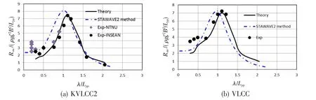
Fig.5 Added resistance at different speeds
3.2 Different component analysis
Fig.6 shows the results of two different components of the added resistance by using two methods.It can be observed that the peak values of ordinate are at λ/Lpp=0.5 and λ/Lpp=1.0 respectively for theoretical and empirical methods.The added resistance due to diffraction is the main component,so the main reason for underestimating the added resistance in short waves is due to the fact that the diffraction resistance is less than that experiment values.The maximum of radiation resistance of empirical results occurs at lower frequency than indicated by theory results.The peak value is influenced by the radiation resistance.In fact the uncertainty in the added resistance measurements is larger[14],especially for low speed ships,so it is difficult to obtain accurate results in the short wave range.For practical predictions,adequate margin is necessary.Other numerical method such as CFD is influenced by grid density and is limited to predict the short wave resistance.It is technically feasible to improve the existed methods based on the analysis of theoretical and semi-empirical methods and tank test data.
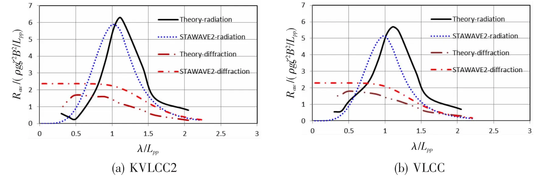
Fig.6 Compenents of added resistance
3.3 Revised STAWAVE2 method
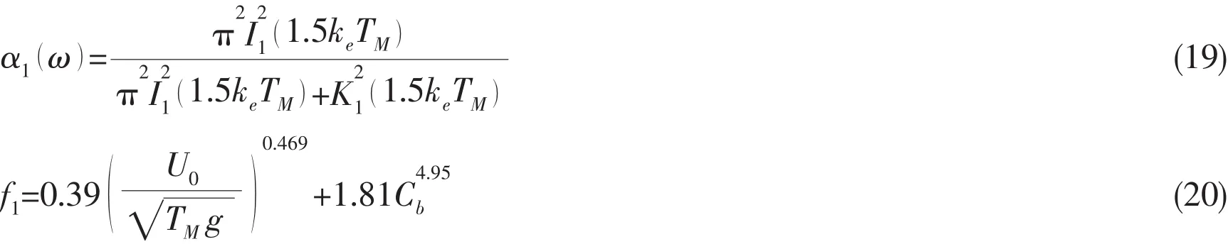
An improved expression for radiation resistance can be found to improve the accuracy of prediction according to comparable analysis of calculated results and test data.The formula is given as:
The coefficients of b1and d1in Eq.(12)can be adjusted to agree the test data better,like the correction of Rob[14],but the database from different institute may be different.The equation fitted by calculated results can be expressed by:
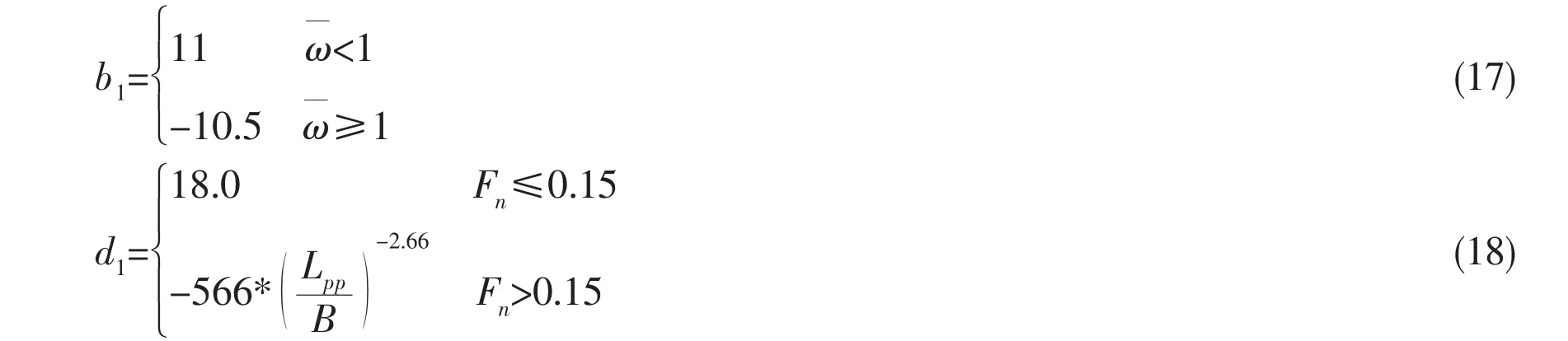
Eq.(14)is limited to extend to the prediction for modern VLCC because it is applicable to the blunt bow shape at low speed,and meets the assumption of vertical plane barrier.A blunt coefficient which reflects waterline shape can be used to improve the accuracy of prediction,but the practical calculation for this coefficient is not easy and actual ship data of different ship type is fluctuated.The following equation can be given through a number of numerical tests:
As is expected,it is seen the added resistance in a wide range of wavelength is in good agreement with experimental data,and the maximum added resistances occur at reasonable wavelengths for two ships.The added resistance of STA2 correction method is shown in Fig.7.
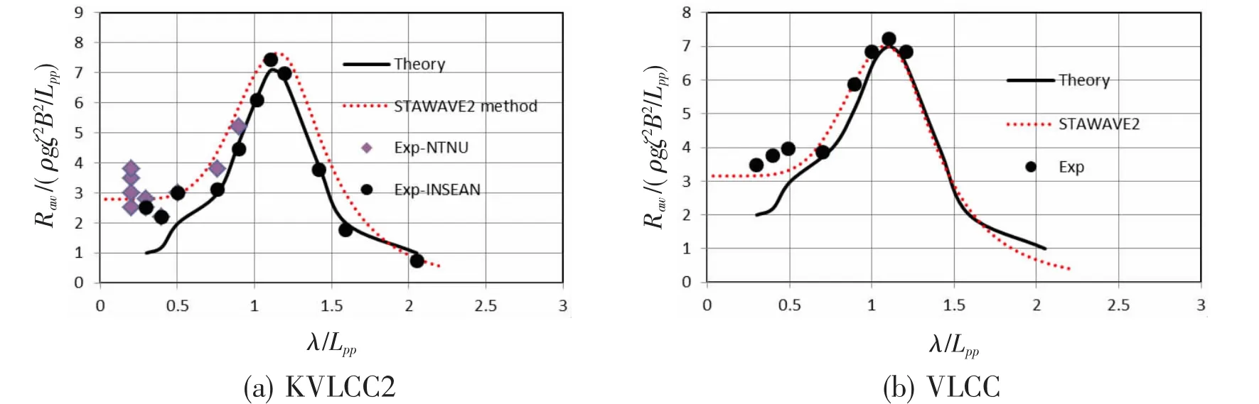
Fig.7 Added resistance of STA2 correction method
In order to validate the applicability to the draught effect,the VLCC case in the ballast condition(T=10 m)is chosen.The performance of VLCC navigation in the ballast condition is often needed for ship owners.For the case of Fr=0.144,results of theoretical and corrected STAWAVE2 method are shown in Fig.8.It is seen that present correction results agree well with the experiment values.It is stressed that the present empirical method is limited to the geosim ships of VLCC type.
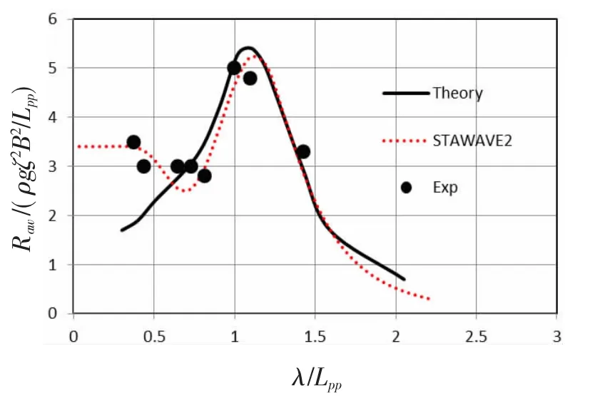
Fig.8 Added resistance of VLCC at ballast draft
4 Conclusions
Hydrodynamic coefficients and wave forces are solved by 3-D panel method based on the horizontal line segment translating and pulsating source panel,and added resistance due to the radiation is obtained by 3D radiation energy method for ships,while one due to the diffraction is obtained by the second order steady-state force formula.STAWAVE2 method recommended by ISO15016-2015 is adopted as the semi-empirical method.Improved formulas are presented based on analysis of calculated results.Conclusions are summarized:
(1)Theoretical results indicate that the maximum of added resistance agrees with experi-mental data,but underestimate the added resistance in the relative short wave range.The modern numerical method based on line integration is shown a higher efficiency than traditional BEM.In this paper,the hull is divided into discrete elements of 1 300,and cases are computed on a computer with Intel Core I5(3.2 GHz).For each frequency calculation,about 3.9 minutes are needed.
(2)The differences between the results of STAWAVE2 and experiment method are large.Improved formulas are presented and the results based on these formulas demonstrate the good agreement can be achieved for VLCC.It can be used to accumulate the database for seakeeping performance.
(3)The present theoretical method predicts the added resistance with good accuracy and high efficiency in the range of medium and long wave for variable speeds and drafts.A notable discrepancy between theory and experiment was found in the range of short wave.

- 船舶力學(xué)的其它文章
- Measurement Method of Sound Impedance of Acoustic Coating in Water-tube without Back Layer
- Buckling of Multi-segment Egg-shaped Pressure Hull
- Effect of Rib Stiffness on Stability of Submerged Ring-stiffened Functionally Graded Cylindrical Shells
- Fatigue Crack Growth Properties of 18Ni(250)and 18Ni(350)Used for Full-Ocean-Depth Pressure Hull
- Research on Stress Intensity Factors for the Deflected Crack of CTS Specimen
- Strength Characteristics of Maraging Steel Spherical Pressure Hulls for Deep Manned Submersibles