
Study on the Hydroelastic Response of Very Large Floating Structures Near Islands and Reefs
2018-10-12 06:28:04
船舶力學(xué) 2018年9期
(China Ship Scientific Research Center,Wuxi 214082,China)
Abstract:A new method was proposed for the numerical simulation of the hydroelastic response of Very Large Floating Structures(VLFS)near islands and reefs with the combination of the Boussinesq equation and the Green function method.The motion response and connector loads were calculated based on this new method and the numerical results were compared with the experimental data.The study in this paper would lay the foundation of the structural design and safety assessment for Very Large Floating Structures and the connectors.
Key words:VLFS(Very Large Floating Structures);hydroelasticity;Boussinesq equation;complex seabed bathymetry;model test
0 Introduction
Very Large Floating Structures(VLFS)deployed near islands and reefs can be used as a floating harbor,logistic base and fishery processing for the development of the natural and tourism resources.In the past decades,extensive investigations have been carried out on the hydroelastic responses of VLFS in the deep open sea by researchers in US and Japan through Project MOB and Mega-Float respectively.The corresponding research findings were published in the international workshop on Very Large Floating Structures[1-4].Shanghai Jiao Tong University also carried out a research on the hydroelastic response of pontoon-type VLFS[5].The environmental condition was assumed to be deep open sea in most of the above research.
The flow field would be strongly influenced by the complex seabed bathymetry near islands and reefs due to the shallow and varying water depth.Therefore the seabed effect on the motion responses and connector loads should be taken into account for the VLFS deployed near islands and reefs.In most of the past research,the complex seabed was treated as a fixed body to calculate its effect on the diffraction and radiation force of the floating structure with the Green function method of finite water depth[6-10].With the support from the National Basic Research Program of China,China Ship Scientific Research Center(CSSRC)was able to carry out a study on the effect of complex seabed bathymetry and non-uniform wave condition on the motion response and connector loads of VLFS near islands or in lagoon and new methods were proposed[11-12].
In the present paper,a new method has been proposed with the combination of the Green function method and the Boussinesq equation which would be called the B-G method for short in this paper.While the Boussinesq equation is introduced for the better simulation of the Froude-Krylov force,the Green function is applied for the calculation of the diffraction and radiation potentials.The numerical predictions and experimental results of the motion response and connector loads of VLFS deployed near islands and reefs are presented following the introduction of the basic theory of the B-G method.
1 Basic theories
In the B-G method,the potential theory is adopted and the fluid is assumed to be ideal with the following assumptions:
(1)The Boussinesq equation is applied to simulate the wave propagation through islands as well as the velocity and pressure field.The Froude-Krylov force is obtained through the pressure integral on the mean wet surface;
(2)The diffraction wave consists of the floating body diffraction and the island diffraction.The former is obtained by the Green function method with the uneven seabed treated as a fixed body while the latter is calculated by the Boussinesq equation;
(3)The radiation potential is also obtained by the Green function method with the uneven seabed treated as a fixed body.
The flow chart of the B-G method was shown in Fig.1.

Fig.1 Flow chart of B-G method
The velocity field and pressure field were obtained by the Boussinesq equation with the following expression:
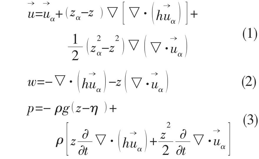
The distribution of velocity and pressure along the water depth shown in Eqs.(1)-(3)was testified and verified through water channel model test[13].
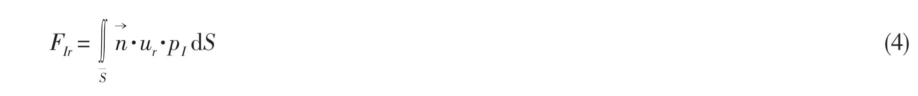
Therefore,the incident wave force of the r-th mode can be obtained through pressure integral as:
The body surface boundary condition of diffraction potential is calculated with incident wave velocity obtained by the Boussinesq equation:

The diffraction and radiation potentials were calculated by the Green function method with the seabed treated as a fixed body:
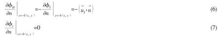
here z=-h( x,y)is the seabed boundary;φris the radiation potential of the r-th mode.The normal derivation of radiation potential is 0 because of the fixed body assumption of the seabed.
2 Model descriptions
The main parameters of VLFS which consists of eight modules and the seabed bathymetry would be introduced in this chapter as well as the finite element model of the VLFS.
2.1 Main parameters of VLFS
The VLFS consists of eight equivalent submersible modules,shown as Fig.2.Each module is 300 m in length,100 m in width and 27 m in height.There is a pair of connectors between adjacent modules at the upper deck.Each connector is 6 m in length and 28 m to the longitudinal section in center plane.The profile of each module and connector are shown in Fig.3 and Fig.4,respectively.
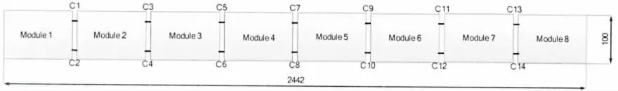
Fig.2 Sketch of VLFS with eight modules
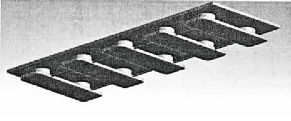
Fig.3 Profile of a single module
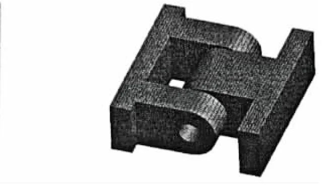
Fig.4 Profile of a connector
The main parameters of VLFS and connector are listed in Tab.1.The connector stiffness(with the consideration of module equivalent stiffness)is shown in Tab.2.
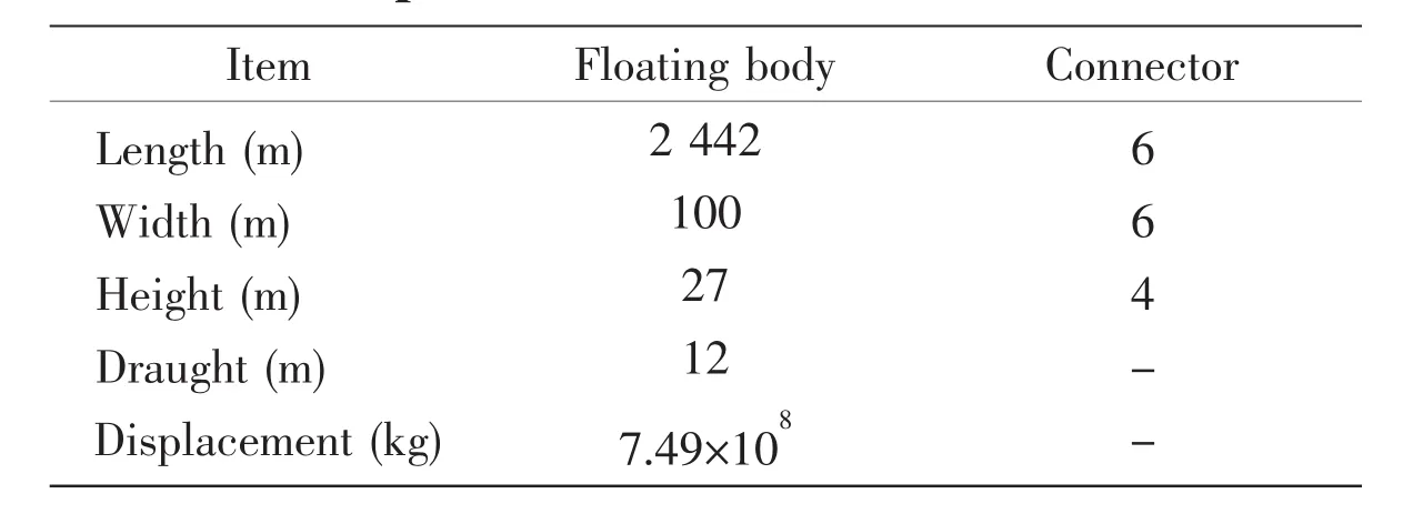
Tab.1 Main parameter of the VLFS and connector
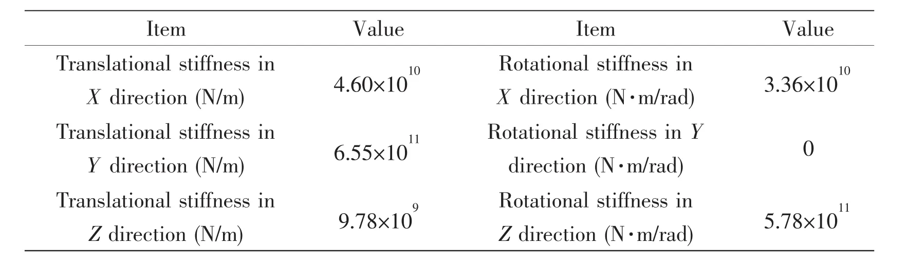
Tab.2 Connector stiffness
2.2 Seabed parameter
The sketch of model test is shown in Fig.5 with the incident wave angle of 90 degrees.The island covers an area of 16.15 m in length and 6.95 m in width.The island model is step like shown as Fig.6 and the above water part is 0.11 m in height with an area of 4.0 m by 1.5 m.There is a mild 2D slope under VLFS,shown as Fig.7.
2.3 Finite element model
Each module was set to be rigid in the finite element model.A mass point with the inertial property of the module was created at the module’s center of gravity.Within the MPC element,the mass point was set to be independent while the elements of the module were set to be dependent on the six degrees of freedom motion of the mass point,shown as Fig.8.The hinge-type connectors are modeled by Bush elements with parameters in Tab.2,shown as Fig.9.
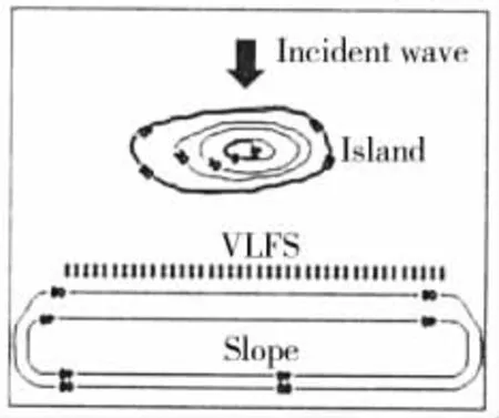
Fig.5 Sketch of model test
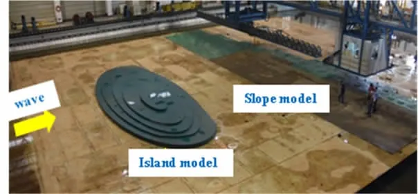
Fig.6 Island model
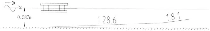
Fig.7 Sketch of slope bottom
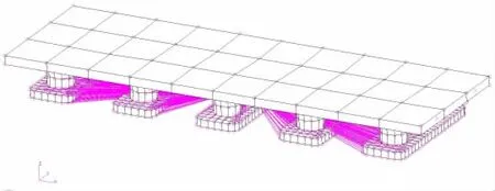
Fig.8 Finite element model of a single module
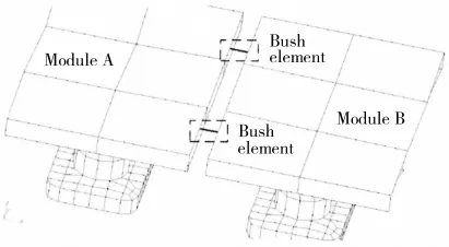
Fig.9 Module connection
3 Numerical results
3.1 Natural frequency and vibration mode
Except for the six global rigid modes,there are seven additional rigid modes,namely relative pitch motion between adjacent modules,due to the hinge type connector.Several typical elastic modes are shown in Fig.10.Despite the rigid module assumption,there are elastic modes such as horizontal bending mode and torsion mode due to the elastic connectors.
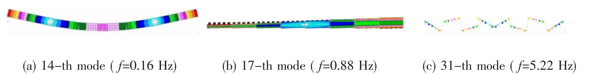
Fig.10 Typical elastic modes of VLFS
3.2 Water wave propagation
In the model test,thirteen wave gauges(W1-W13)were placed in the far field,near islands,around and behind VLFS respectively to study the effect of islands and slope on the wave propagation,shown as Fig.11.
The numerical results and experimental data of wave height at the thirteen wave gauges of two typical regular wave conditions(H=3.0 m,T=7.0 s,13.0 s)are shown in Fig.12.The solid line represents the numerical results while the experimental data is shown in circles.
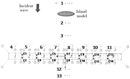
Fig.11 Sketch of model test and wave gauge position
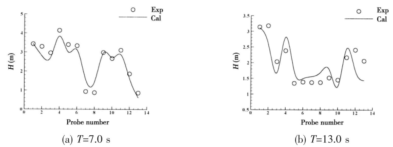
Fig.12 Wave height at each wave gauge
The wave heights at gauges 7 and 8 which are right behind the island are much smaller than the others due to the shadowing effect of the island.
3.3 Motion response
The motion responses of heave,roll and pitch of modules 1 and 4 are shown in Fig.13.The solid line represents the motion response of module 1 while corresponding results of module 4 are shown in circles.The results indicate that the amplitude of motion responses of both modules is close to each other.
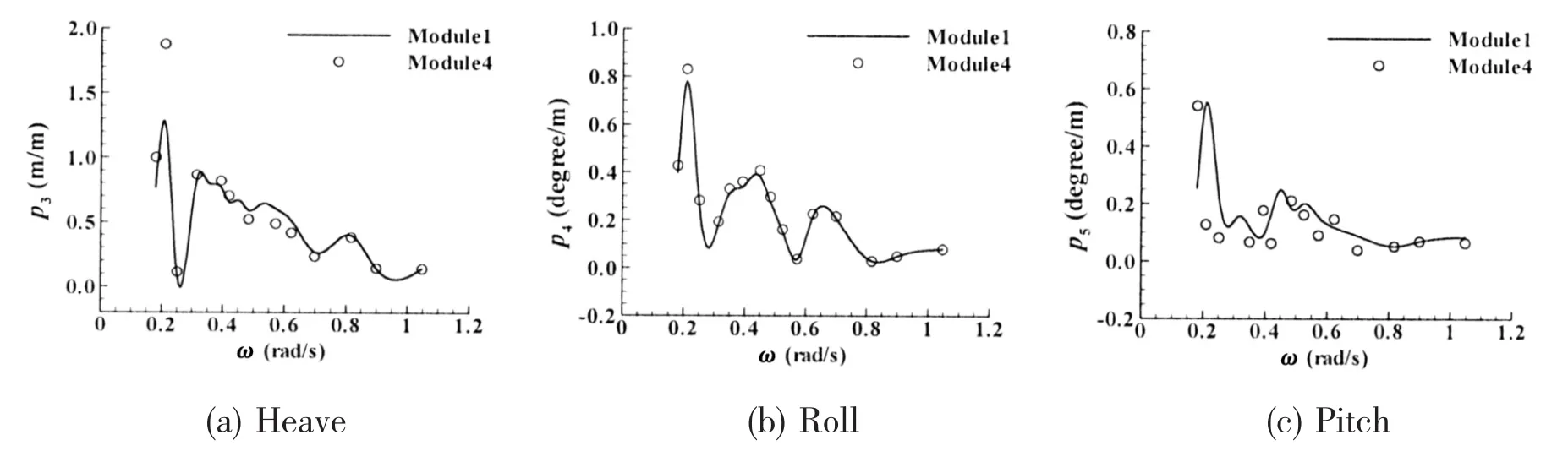
Fig.13 Motion response of modules 1 and 4
Both the numerical results and experimental data of motion responses of module 1 are shown in Fig.14.The solid line represents the numerical results while the experimental data is shown in circles and a fair agreement is reached between them.Due to the inhomogeneous wave caused by the island,there is obvious pitch motion under the incident wave angle of 90 degrees.
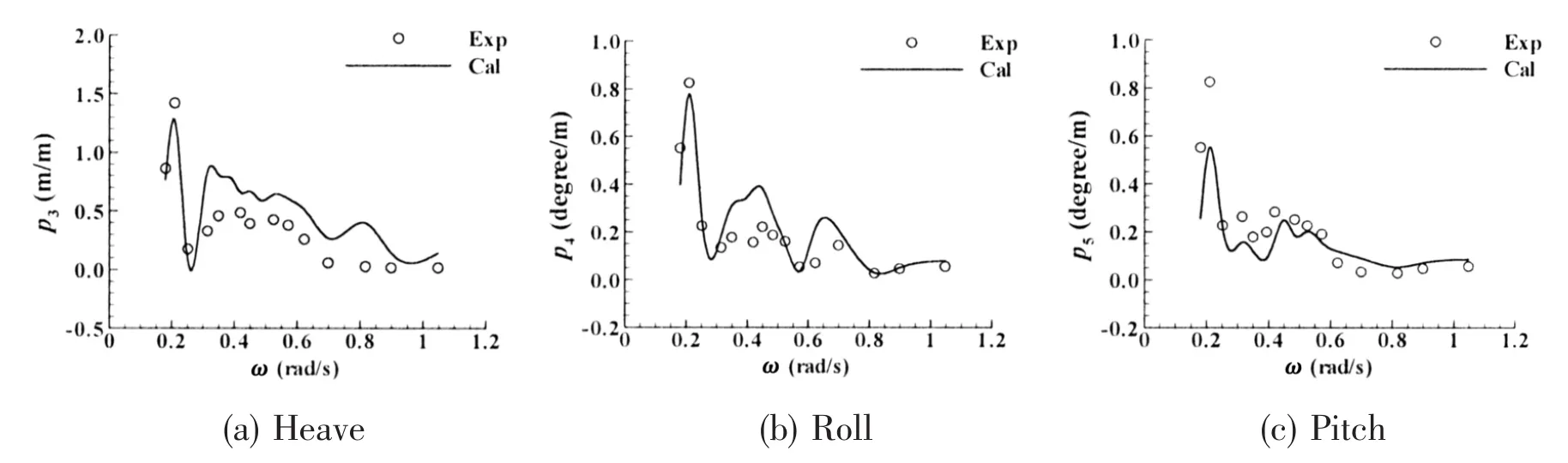
Fig.14 Comparison of numerical results and experimental data of motion responses of module 1
3.4 Connector loads
The transfer function of connector loads in three translational directions of connector 13(C13 in Fig.2)are shown in Fig.15(a)-(c)and the contribution of main modes are shown in Fig.15(d)-(f)where ‘Total’ represents the superposition of all modes.
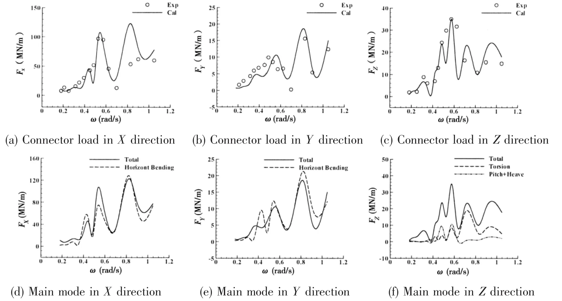
Fig.15 Transfer function of connector loads and main modes
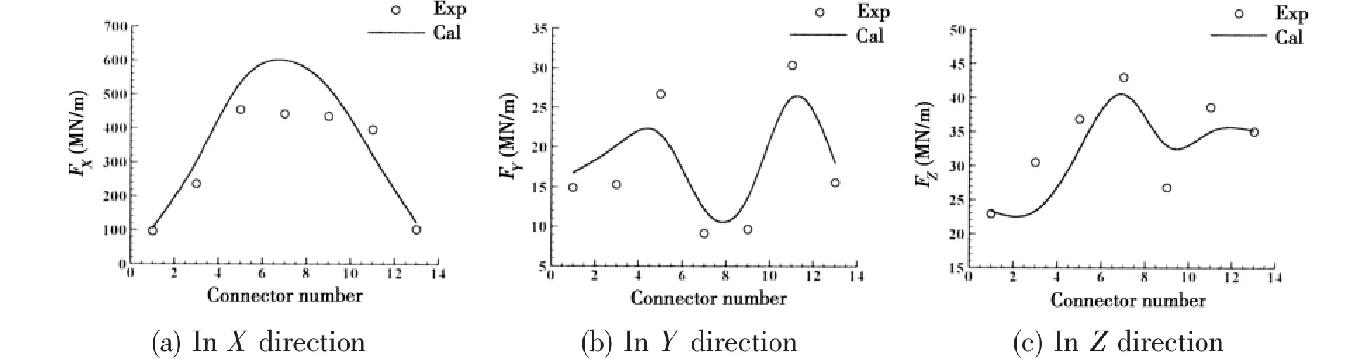
Fig.16 Maximum value of transfer function of connector loads
It is shown in Fig.15 that the connector loads in X and Y directions are mainly contributed by the two node horizontal bending mode(Fig.10(a))while the connector load in Z direction is influenced by the torsion mode(Fig.10(b))and the coupling mode of relative heave and pitch motion between adjacent modules(Fig.10(c)).
The maximum values of connector loads at the income wave side(connectors with odd number in Fig.2)are shown in Fig.16.In X direction,it is obvious that the connector loads at the middle of VLFS are larger than those at both ends while the connector load in Y direction presents an M shape.The connector load in X direction is much larger than that in Z direction while the connector load in Y direction is found to be smallest.
4 Conclusions
Based on the Green function method,a new method was proposed with the introduction of Boussinesq equation for the better simulation of Froude-Krylov force of VLFS deployed near islands and reefs.The motion response and connector loads were calculated by this new method and the results were compared with the experimental data.The following conclusions could be drawn from the study:
(1)The wave height at the middle of VLFS(right behind the island)is much smaller than that at both ends of VLFS due to the shadowing effect of the island;
(2)Due to the inhomogeneous wave caused by the island,there is obvious pitch motion even under the incident wave angle of 90 degrees which is an obvious evidence of island effect on the motion response of VLFS;
(3)The connector loads in X and Y directions are mainly contributed by the two node horizontal bending mode while the connector load in Z direction is influenced by the torsion mode and the coupling mode of relative heave and pitch motion between adjacent modules;
(4)The connector load in X direction is much larger than that in Z direction while the connector load in Y direction with an M shape distribution along the longitudinal direction of VLFS is found to be smallest.
- 船舶力學(xué)的其它文章
- Frequency-domain Response Analysis of Adjacent Multiple Floaters with Flexible Connections
- Hydroelasticity of a Barge with Varying Bathymetry
- Study on the Performance of Spherical Tail Bearing based on Finite Element Method
- Experimental Study on Dwell-fatigue of Titanium Alloy Ti-6AL-4V for Offshore Structures
- Dynamic Property and Motion Simulation of Atmospheric Diving Suit
- Investigation on Higher-Order Responses of Vortex-Induced Vibration for a Mounted Cylinder