
High-speed water impacts of flat plates in different ditching configuration through a Riemann-ALE SPH model *
2018-04-13 12:23:32MarroneColagrossiChironDeLeffeLeTouz
水動力學(xué)研究與進(jìn)展 B輯 2018年1期
S. Marrone, A. Colagrossi,L. Chiron,M. De Leffe,D. Le Touzé
?
High-speed water impacts of flat plates in different ditching configuration through a Riemann-ALE SPH model*
S. Marrone1, A. Colagrossi1,L. Chiron2,M. De Leffe2,D. Le Touzé3
1.2.3.

Aircraft ditching, high-speed water entry, smoothed particle hydrodynamics (SPH)
Introduction
The problem of the high-speed water entry is classically of interest in the naval field as far as slamming loads on ships are concerned. In this context several theoretical solution have been derived for simplified conditions and a large literature of experi- mental data is available. Water-entry problems are also very important in the aircraft ditching, that is, the emergency landing on water. The response of the vehicle to this kind of water impact is critical in terms of safety of the passengers and certifications issued by airworthiness authorities includes the success of the airframe in ditching tests. In this context few high- fidelity numerical methods have been developed so far[1, 2].
The smoothed particle hydrodynamics (SPH) method has already shown promising results for the simulation of violent water impacts thanks to its accuracy and easiness in following the free-surface deformations[3-5]. In the present work an in-depth study and validation of the SPH model is provided for 2-D water entries of flat panels with small deadrise angle. Both purely vertical and oblique impact velo- city with high horizontal velocity component are studied (Sections 2 and 3). These conditions are of interest for, respectively, helicopter and airplane ditching situations. To this aim the numerical outcome will be compared to experimental measurements and analytical solutions when available. The influence of the 3-D effects are also addressed for the oblique water entry through a 3-D SPH model. In order to accurately resolve the high and localized pressure peaks developed at the impact a Riemann-based SPH solver is used within an arbitrary Eulerian-Lagrangian (ALE) framework. The choice of the numerical para- meters to be adopted, as e.g., the liquid compressi- bility, is critically and extensively discussed on the base of physical considerations peculiar of water- impact flows.
1. Adopted SPH scheme
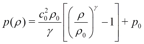
In the present work Euler equations for com- pressible fluids are solved. Indeed, since the Reynolds number of the flow is quite high and only the impact stage is simulated (short time-range regime) viscous effects can be considered negligible. The weakly-com- pressible model is adopted, the fluid is, therefore, assumed to be barotropic and a classical stiffened state equation is used

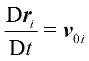
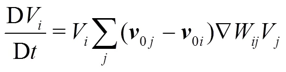
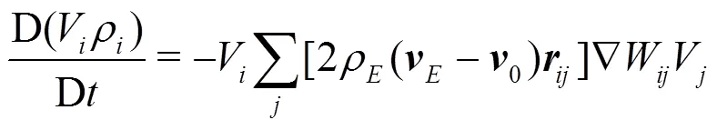
In the present work the Riemann-based solver described in Ref. [7] is adopted. In that work the ALE formalism is used allowing for maintaining a regular particle spatial distribution and smooth pressure fields while preserving the whole scheme conservation and consistency of the classical SPH scheme. The intro- duction of the Riemann-based solver in the SPH scheme leads to an increased stability and robustness of the scheme with respect to the standard SPH formulation. The formalism proposed by Ref. [8], Thanks to the introduction of Riemann-solvers the fluxes between particles are upwind oriented and the resulting scheme is characterized by good stability properties. The discrete Euler equations are written as follows:
2. Vertical water entry of a flat panel

As described in the theoretical work by Ref. [10], for these small deadrise angles a very thin, high-speed jet of water is formed, and the time-spatial gradients of the pressure field are extremely high. This makes the test conditions very demanding for numerical solvers. From the potential flow theory by Ref. [10], the jet thickness at model scale is about 0.1 mm. It is worth noting that the theory in Ref. [10] is formulated for symmetric wedge impacts whereas in the present casetheimpactofan inclined single plate is consi- dered. More details about the reference solution to be adopted are given in Section 2.2.
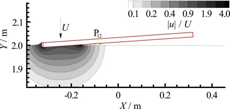
Fig. 1 (Color online) Vertical impact of a flat panel. Contour lines are representative of the SPH velocity intensity. Pressure probe number 12, which is the gauge used for the comparison with the experimental data, is also depicted

As noted in Ref. [11], this very thin, high-speed jet disintegrates at some distance from the root due to interaction with both the surrounding air and the surface of the body. In this case surface tension plays an important role on the jet evolution. This local and complex physics is not taken into account in the present numerical method but it is not supposed to play are relevant role on the pressure distribution.
2.1 Selection of the speed of sound for the SPH model
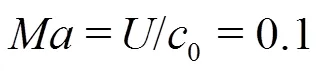
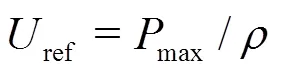
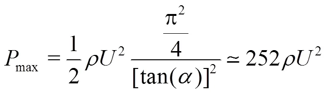
corresponding to about 9.1′106Pa in our experiment.
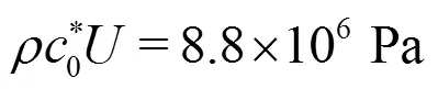
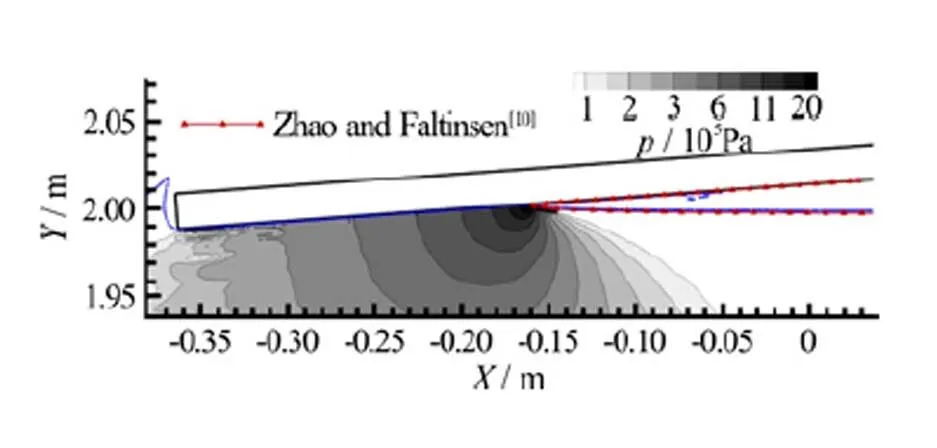
Fig. 2 (Color online) Vertical impact of a flat panel: Contour lines are representative of the SPH pressure field. Red solid line is the free surface extracted from Ref. [10]
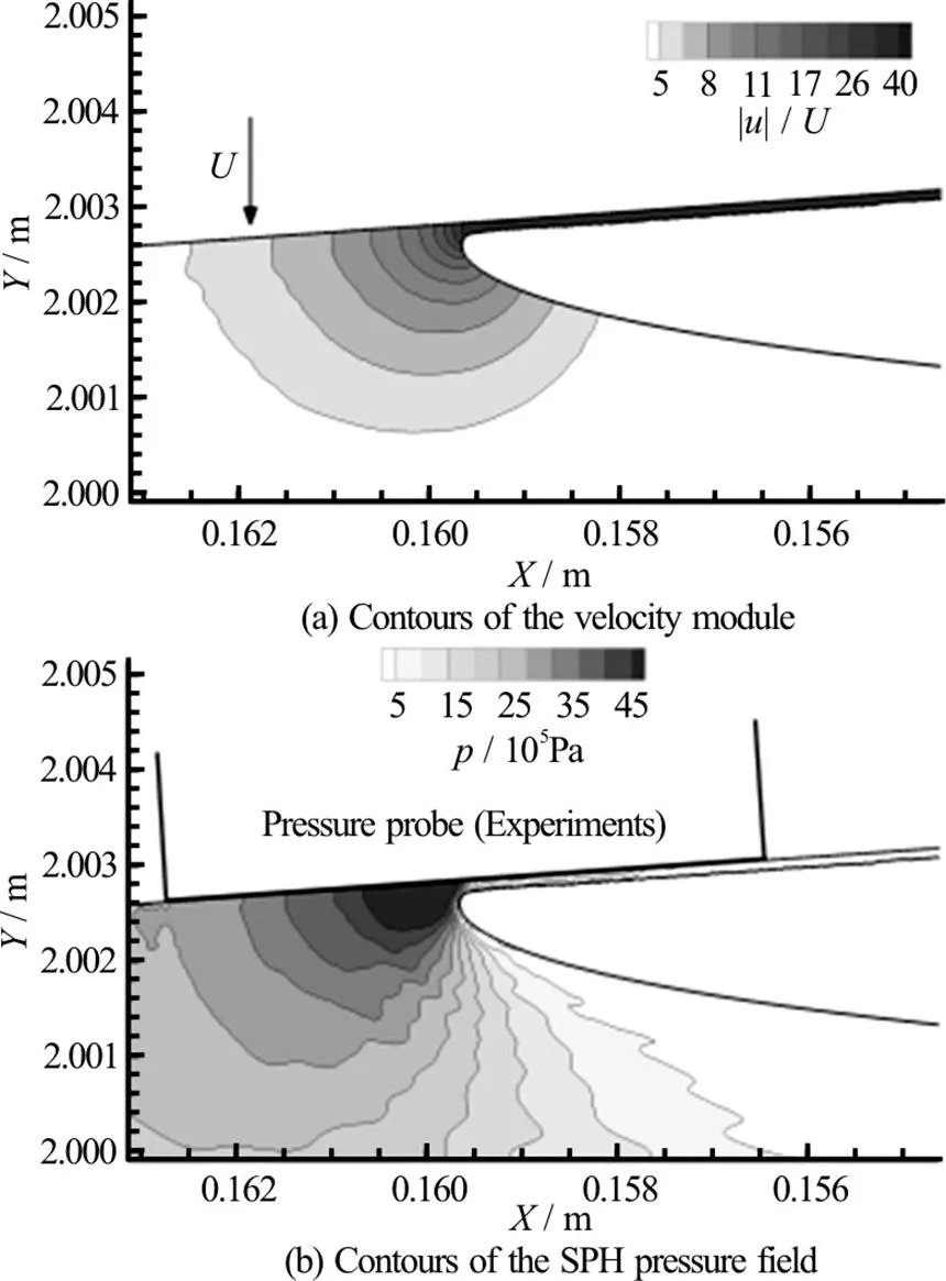
Fig. 3 Vertical impact of a flat panel: Enlarged view of the impact zone. The size of the pressure gauges used in the experiments is also depicted
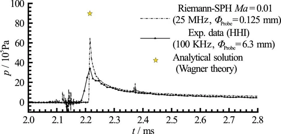
Fig. 4 (Color online) Vertical impact of a flat panel: SPH pressure time histories at probe P12 compared with experimentaldataandwithanalyticalsolution (Wagner theory)
2.2 Comparison between SPH results, analytical solution and experimental data
In the right plot of the same figure an enlarged view of the pressure field is shown (in this case the displayed pressure range is enlarged too). From this plot it is seen that the high-pressure region is limited to an area of 1 mm2with a pressure peak of about 6.0′106Pa. In the same figure the size of the probe used in the experiments is depicted. Clearly, the pressure sensor or has a size much larger than the pressure bulb formed below the water-jet root. This aspect will be discussed in the following section.
In Fig. 4 the time histories of the pressure mea- sured at probe P12 are shown. This probe is posi- tioned 0.236 m from the left-hand edge of the panel (see Fig. 1). The SPH solution is compared with the experiments and with the pressure peak predicted by Wagner theory. The SPH prediction is between the two reference data sets, and is characterized by high-frequency components due to the fragmented jet of water that pass over the numerical pressure probe. The latter has a dimension of 0.125 mm (which is the size of the SPH kernel support) and the SPH sampling rate is 25 MHz. Both the SPH and the analytical predictions overestimate the experimental data for which the maximum pressure recorded is 3.4′106Pa (in the SPH solution the pressure peak reaches 7.0′106Pa whereas the analytical prediction is 9.1′106Pa). It has to be noted that, even though the Wagner theory is referred to the case of asymmetric wedge entry, according to Refs. [14] and [15] the value of the pressure peak should be substantially the same of the case of an oblique flat panel impact (it will be shown in Section 2.3 that this approximation can be quite rough for the present case).

(1)Changes of the body velocity during the impact stage.
(2)Rotations of the body during the impact stage.
(3)Deformations of the wedge surface.
(4)Sampling rate of the pressure signals.
(5)Size of the pressure gauge.
Thanks to the experimental setup adopted the first three points can be neglected, while the last two can play an important role. In order to take into account the experimental sampling rate, the SPH signal has first been filtered using a moving average filter (MAF) reducing the numerical sampling rate from 25 MHz to 100 kHz. The result is illustrated in Fig. 5. The reduction of the SPH peak due to this filtering procedure is not enough to get a good agree- ment with the experimental data. As a further step the SPH pressure has been measured integrating on a circular area equal to the size of the experimental pressure probes and then filtered at 100 kHz. This result is shown in Fig. 6. In this case the SPH output is much closer to the pressure recorded in the experi- ment.
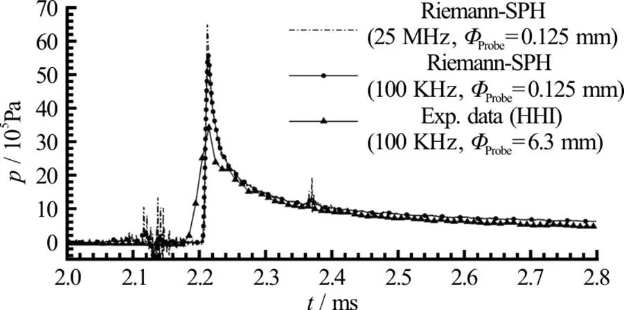
Fig. 5 Vertical impact of a flat panel: SPH pressure time histories versus experimental data. The SPH signal is filteredwitharunningaveragefilters(MAF)at100 kHz (dashed-dotted line)
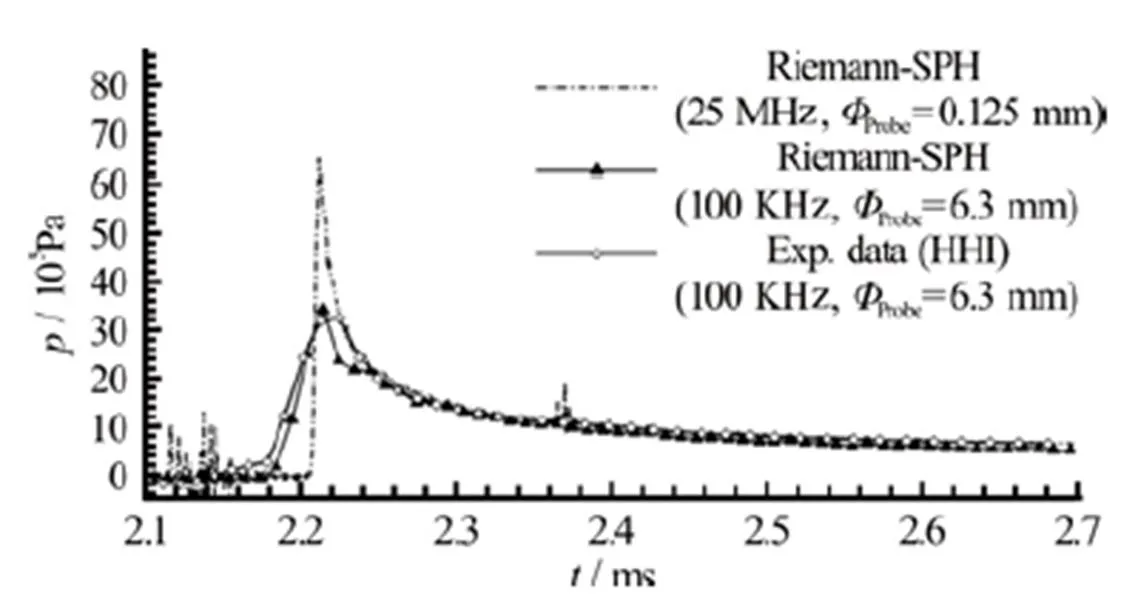
Fig. 6 Vertical impact of a flat panel: SPH pressure time histories versus experimental data. The SPH signal recorded using the size of the experimental pressure gauges and filtered at 100 kHz is also shown

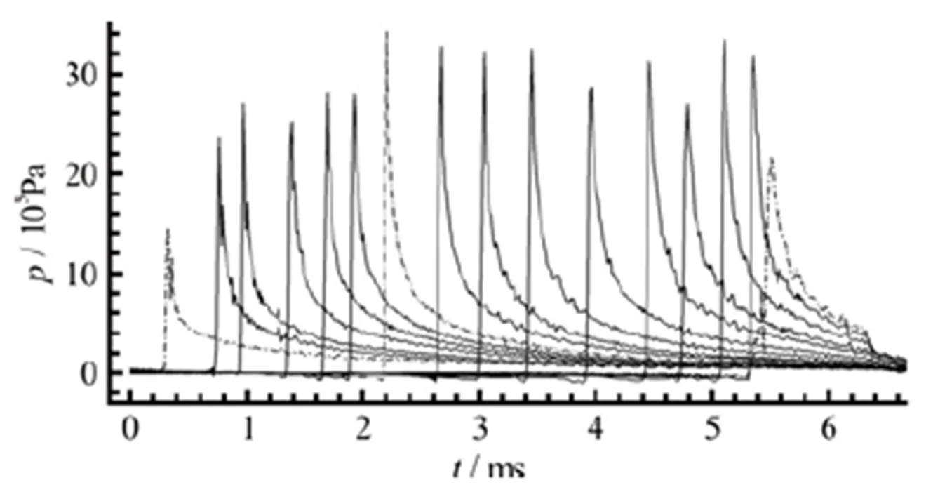
Fig. 7 Vertical impact of a flat panel: experimental data for the pressure time histories on a row of probes (not equi- spaced). The time history from the first and last probes on the panel impacting the water are represented with dashed-dotted line. The time history in dash dot-dot line is from probe P12 , used in the previous figures for comparison with the SPH solution

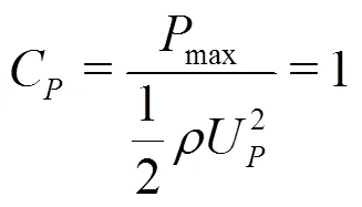
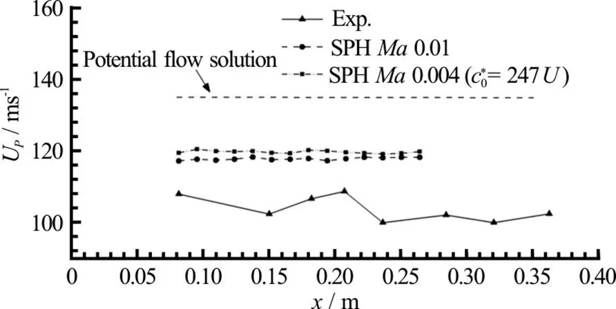
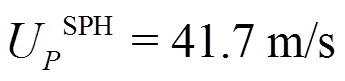
Fig.9 Vertical impact of a flat panel: Peak propagation velocity calculated on several positions along the panel for the experiment (triangles), SPH simulation at (circles) and (squares), and analyti- cal value from potential flow theory (dashed line). The origin of the axis is set at the left-hand edge of the panel

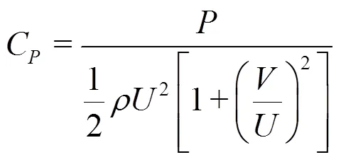
Table 1 Average of the peak propagation velocity plotted in Fig. 9. The corresponding pressure peak , the actual average pressure peak measured at the probes and the related pressure coefficient (Eq. (4)) are also reported
2.3 Comparison between symmetric and asymmetric water entry
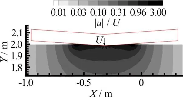
Fig.10 (Color online) Vertical impact of a flat panel: fluid domain adopted in the symmetric problem configura- tion. Contours refer to the module of the velocity field
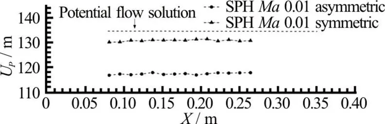
Fig.12Vertical impact of a flat panel: pressure time histories of symmetric (solid line) and asymmetric (dashed) solutions measured at 0.16 m from the left-hand edge of the panel. Analytical solutions by Ref. [21] (dash-dot line) and by Ref. [10] (dash dot-dot line) are also reported
3. Water entry with high horizontal speed
In this section the ditching problem including a large horizontal velocity component is studied, com- paring the SPH out come to model test experiments. Given the higher complexity of the problem, in this section also possible 3-D effects are investigated, as their role is expected to be not negligible for this case.
3.1 Description of the experimental data
Guided ditching impact experiments[19, 23]were performed in the CNR-INSEAN towing tank, which is 470 m long, 13.5 m wide and 6.5 m deep. The dimension of the flat plate were 0.5 m by 1 m (Fig. 13). Pressures at 18 points are measured through Kulite XTL123B pressure transducers. The sampling rate of the latter is 200 kHz while their dimension is 3.8 mm. The horizontal and vertical velocities at the impact are respectively 40 m/s and ?1.5 m/s. In the experiments, these velocities are assumed to remain constant during the whole ditching impact.
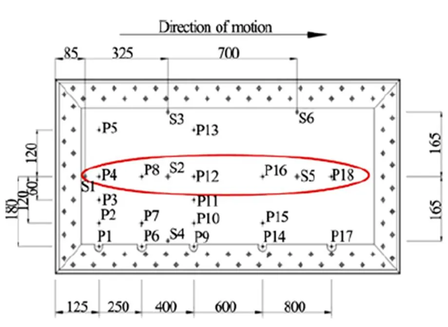
Fig.13(Color online) Top view of the plate adopted in the ditching experiments. The ellipse shows pressure probes considered for 2-D SPH simulations (mm)
3.2 Numerical methodology
In this second test case series, simulations have been conducted using adaptive particle refinement (APR) technique[24]. This technique allows keeping a high spatial resolution around the flat plate during the simulation as the refinement areas move at the same speed of the plate. In order to avoid the pressure filtering described in Section 2, the numerical adopted pressure sensor size is the same as in the experiments (i.e., 3.8 mm).
3.3 Impact at pitch angle
Another important aspect to discuss is the ampli- tude of the pressure peak. Indeed, looking at top plots of Fig. 16, one could be induced to conclude that the 2-D SPH matches very well the 3-D experimental measurements. This would be a misleading judgement since it would be in contrast with the different peak propagation velocities (according to correlation pro- vided in Eq. (4)). This apparent contradiction can be explained observing that at probe P16 (bottom plot of Fig. 16) the SPH pressure peak is about 50% higher than at probes P4 and P8. The latter presents also more noisy signals and a less clear convergence. The reason is linked to the fact that at the beginning of the impact there are only few particles to resolve the impact region, while going forward in time the peak region grows in amplitude, i.e., it is better resolved.
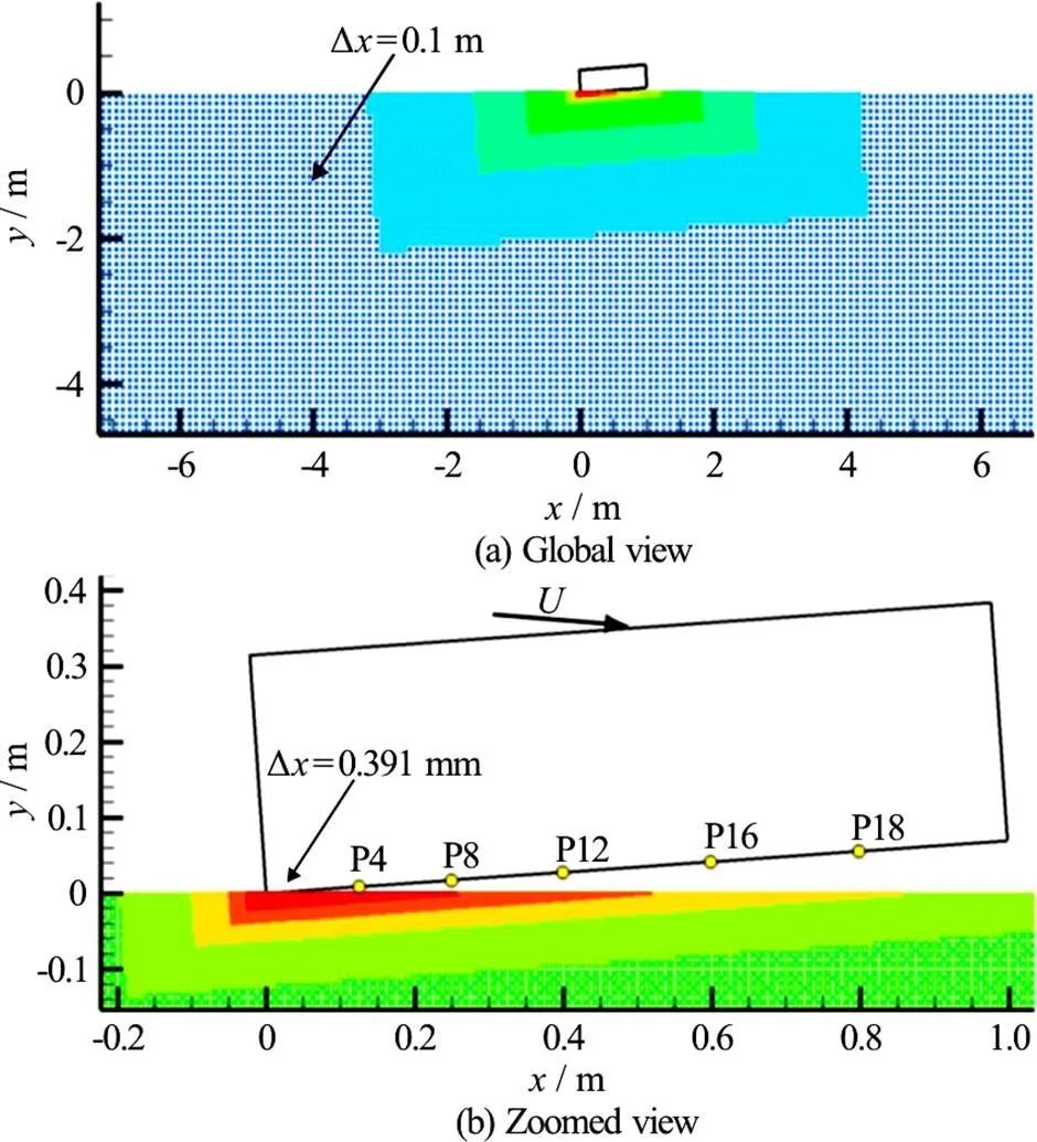
Fig.14(Color online) Sketch of the oblique ditching simulation involving 8 refinement levels. Contours refer to refine- ment level
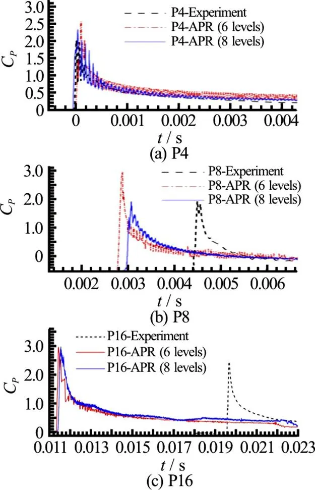
Fig.16(Color online) Comparison between experimental data and 2-D SPH simulations with different refinement levels at probes P4, P8, P16
3.4 Impact at pitch angle: 2-D and 3-D solu- tions


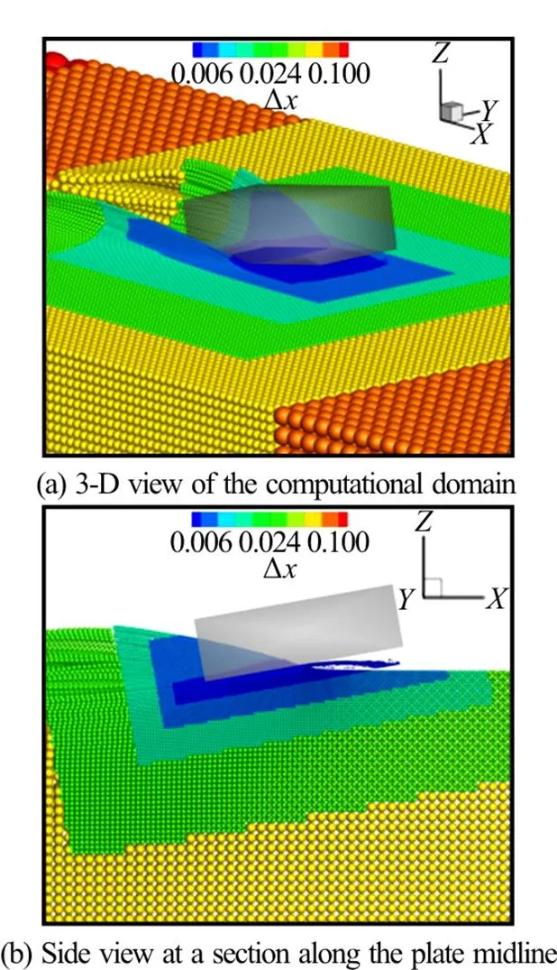
Fig.19(Color online) 3-D SPH simulation with APR. Contours refer to the local particle size
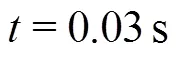
The latter can be also observed in Fig. 21, where a top view of the pressure field is provided. The delay of the spray root close to the lateral edges of the plate is visible in then nearly-parabolic shape of pressure peak front.
In Fig. 22 the comparison between 2-D and 3-D SPH pressure signal at P16 is provided. The 3-D solution is much closer to the experimental data with respect to the 2-D simulation. It can be clearly seen that the 3-D effects induce a decrease of the peak amplitude and a delay of the peak occurrence, as consequence of the lower peak propagation velocity. This confirms the conjecture in Ref. [19] regarding the large discrepancies between 2-D potential flow solu- tion and experiments.
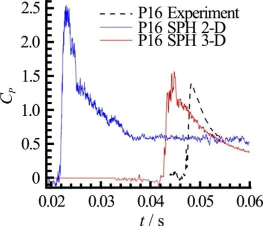
Fig.22(Color online) Comparison of the pressure signal registered at probe P16 between experiments, 2-D and 3-D SPH simulations
4. Concluding remarks
High speed ditching problems, in both vertical and oblique entry velocity have been discussed. All along the paper the main flow characteristics consi- dered are the pressure signal and the jet propagation velocity (i.e., pressure peak propagation velocity) which are strictly correlated.
Then, analysis has been focused on ditching problems of flat plates with high horizontal velocity, comparing to the experimental data and potential flow solution in Refs. [23] and [19]. For this case, an Adaptive Particle Refinement strategy has been adopted to limit the computational costs.
Then, a 3-D simulation for the case at 10° is performed recovering the agreement with the experi- mental data and showing that, as speculated in Ref. [19], 3-D effects are substantial for this problem for both the pressure peak amplitude and the jet propagation velocity.
Acknowledgements
The research leading to these results has partially received funding from the European Union’s Horizon 2020 Research and Innovation Programme (Grant No. 724139). The SPH simulations performed under the present research have been obtained using the SPHFlow solver, software developed within a collaborative consortium composed of Ecole Centrale de Nantes, Next Flow Software company and CNR-INSEAN.
[1] Streckwall H., Lindenau O., Bensch L. Aircraft ditching: A free surface/free motion problem [J]., 2007, 7(3): 177-190.
[2] Guo B., Liu P., Qu Q. et al. Effect of pitch angle on initialstage of a transport airplane ditching [J]., 2013, 26(1): 17-26.
[3] Oger G., Doring M., Alessandrini B. et al. Two-dimen- sional SPH simulations of wedge water entries [J]., 2006, 213(2): 803-822.
[4] Meringolo D. D., Colagrossi A., Marrone S. et al. On the filtering of acoustic components in weakly-compressible SPH simulations [J]., 2017, 70: 1-23.
[5] Lind S., Stansby P., Rogers B. D. In compressible-com- pressible flows with a transient discontinuous interface using smoothed particle hydrodynamics (SPH) [J]., 2016, 309: 129-147.
[6] Marrone S., Colagrossi A., Di Mascio A. et al. Prediction of energy losses in water impacts using incompressible and weakly compressible models [J]., 2015, 54: 802-822.
[7] Oger G., Marrone S., Le Touzé D. et al. SPH accuracy improvement through the combination of a quasi- Lagrangian shifting transport velocity and consistent ALE formalisms [J]., 2016, 313: 76-98.
[8] Vila J. On particle weighted methods and smooth particle hydrodynamics [J]., 1999, 9(2): 161-209.
[9] Marrone S., Colagrossi A., Park J. et al. Challenges on the numerical prediction of slamming loads on LNG tank insulation panels [J]., 2017, 141: 512-530.
[10] Zhao R., Faltinsen O. M. Water entry of two-dimensional bodies [J]., 1993, 246: 593-612.
[11] Korobkin A. A., Iafrati A. Numerical study of jet flow generated by impact on weakly compressible liquid [J]., 2006, 18(3): 032108.
[12] Campana E., Carcaterra A., Ciappi E. et al. Some insights into slamming forces: compressible and incompressible phases [J]., 2000, 214(6): 881-888.
[13] Korobkin A., Pukhnachov V. Initial stage of water impact [J]., 1988, 20: 159-185.
[14]Faltinsen O. M., Semenov Y. A. Nonlinear problem of flat-plate entry into an incompressible liquid [J]., 2008, 611: 151-173.
[15]Okada S., Sumi Y. On the water impact and elastic response of a flatplate at small impact angles [J]., 2000, 5(1): 31-39.
[16]Chuang S. L. Experiments on slamming of wedge-shaped bodies [J]., 1967, 11(3): 190-198.
[17]Mizoguchi S., Tanizawa K. Impact wave loads due to slamming-A review [J]., 1996, 43(4): 139-154.
[18]Tenzer M., Moctar O. E., Schellin T. E. Experimental investigation of impact loads during water entry [J]., 2015, 62(1): 47-59.
[19] Iafrati A. Experimental investigation of the water entry of a rectangular plate at high horizontal velocity [J]., 2016, 799: 637-672.
[20]Armand J., Cointe R. Hydrodynamic impact analysis of a cylinder [J]., 1987, 109(3): 237-243.
[21] Watanabe T. Analytical expression of hydrodynamic im- pact pressureby matched asymptotic expansion technique [J]., 1986, 71: 77-85.
[22]Semenov Y. A., Iafrati A. On the nonlinear water entry problem of asymmetric wedges [J]., 2006, 547: 231-256.
[23]Iafrati A., Grizzi S., Siemann M. et al. High-speedditching of a flat plate: Experimental data and uncertainty assess- ment [J]., 2015, 55: 501-525.
[24] Chiron L., Oger G., de Leffe M. et al. Analysis and impro- vements of adaptive particle refinement (APR) through CPU time, accuracy and robustness considerations [J]., 2018, 354: 552-575.
(October 22, 2017, Accepted December 21, 2017)
?China Ship Scientific Research Center 2018
S. Marrone (1983-), Male, Ph. D.
S. Marrone,
E-mail:salvatore.marrone@cnr.it

- 水動力學(xué)研究與進(jìn)展 B輯的其它文章
- Spectral/hp elementmethods:Recent developments,applications, and perspectives *
- Modeling of single film bubble and numerical study of the plateau structure in foam system *
- Influence of upstream disturbance on the draft-tube flow of Francis turbine under part-load conditions *
- Numerical study of the wave-induced slamming force on the elastic plate based on MPS-FEM coupled method *
- Gas-liquid flow splitting in T-junction with inclined lateral arm *
- 3-D Lagrangian-based investigations of the time-dependent cloud cavitating flows around a Clark-Y hydrofoil with special emphasis on shedding process analysis *