
Modified fast Fourier transform in FBMC for satellite communications
2017-11-20 02:39:56ChosnYANGRongkeLIURuifengDUAN
CHINESE JOURNAL OF AERONAUTICS 2017年4期
Chosn YANG,Rongke LIU,*,Ruifeng DUAN
aSchool of Electronic and Information Engineering,Beihang University,Beijing 100083,China
bSchool of Information Science and Technology,Beijing Forestry University,Beijing 100083,China
Modified fast Fourier transform in FBMC for satellite communications
Chaosan YANGa,Rongke LIUa,*,Ruifeng DUANb
aSchool of Electronic and Information Engineering,Beihang University,Beijing 100083,China
bSchool of Information Science and Technology,Beijing Forestry University,Beijing 100083,China
In this paper,a Doppler scaling fast Fourier transform(Doppler-FFT)algorithm for filter bank multi-carrier(FBMC)is proposed,which can efficiently eliminate the impact of the Doppler scaling in satellite communications.By introducing a Doppler scaling factor into the butterfly structure of the fast Fourier transform(FFT)algorithm,the proposed algorithm eliminates the differences between the Doppler shifts of the
subcarriers,and maintains the same order of computational complexity compared to that of the traditional FFT.In the process of using the new method,the Doppler scaling should be estimated by calculating the orbital data in advance.Thus,the inter-symbol interference(ISI)and the inter-carrier interference(ICI)can be completely eliminated,and the signal to interference and noise ratio(SINR)will not be affected.Simulation results also show that the proposed algorithm can achieve a 0.4 dB performance gain compared to the frequency domain equalization(FDE)algorithm in satellite communications.
?2017 Chinese Society of Aeronautics and Astronautics.Production and hosting by Elsevier Ltd.This is an open access article under the CC BY-NC-NDlicense(http://creativecommons.org/licenses/by-nc-nd/4.0/).
1.Introduction
Filter bank multi-carrier(FBMC)is a promising modulation technology in satellite communications,since it can obtain a higher spectral efficiency than those of existing modulations.1–3Moreover,as FBMC is a competitive candidate in 5G networks,we can have better interactivity between satellite and terrestrial communication networks by using FBMC on both sides.4However,due to the Doppler effect,inter symbol interference(ISI)and inter carrier interference(ICI)come along with FBMC in satellite communications,and the excessive peak-to-average power ratio(PAPR)makes subcarriers sensitive to non-linear distortion.
The Doppler effect contains Doppler shift and Doppler scaling in multi-carrier systems.The Doppler shift is the frequency deviation of a carrier between a receiver and a transmitter,and the Doppler scaling is the difference in frequency shift between subcarriers.We usually use the frequency offset estimation,which is a mature technology,to eliminate the impact of the Doppler shift.5,6In this paper,we will solve the Doppler scaling problem caused by a rapid relative movement.The relative speed is merely tens of meters per second in terrestrial communication systems,whereas the relative speed can be several kilometers per second in low earth orbit(LEO)satellite communication systems.Since the Doppler scaling factor is proportional to the relative speed between two communications,the Doppler scaling problem cannot be ignored in satellite communication systems.
Among existing methods,the frequency domain equalization(FDE)and the non-uniform fast Fourier transform(NUFFT)can reduce the impact of the Doppler scaling.The FDE processes received signals in the frequency domain,and modifies the frequency error by a feedback mechanism.7–9However,it could not eliminate the impact of the Doppler scaling completely.The NUFFT can solve the Doppler scaling problem completely by resetting the frequencies of all subcarriers,10–12but the high computational complexity makes it inapplicable to satellite communications.
In this paper,we propose a Doppler scaling fast Fourier transform(Doppler-FFT)algorithm to eliminate the impact of the Doppler scaling.By employing a Doppler modifying factor in the butterfly process unit of FFT,the Doppler-FFT can adjust the frequency intervals of subcarriers to the right values.Moreover,since we only introduce a constant factor to the FFT,the Doppler-FFT has the same complexity as that of the traditional FFT,and it can use the accelerating methods for the FFT as well.
2.FBMC on satellite channel
2.1.SMT signal
We firstly briefly review the offset quadrate amplitude modulation/staggered modulated multitone(SMT)signal,which is one of the FBMC signals.The structure and the symbol block of SMT are shown in Figs.1 and 2,respectively,whereandare the real and imaginary parts of thenth symbol in themth transmitted subcarrier,respectively,Tis a symbol time,P(w)is the prototype filter of PHYDYAS,13Q(w)is the satellite channel,andare the estimated values for the real and imaginary parts of thenth symbol in themth received subcarrier,respectively.
The prototype filterP(w)is expressed asp(t)in the time domain as
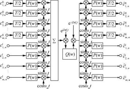
Fig.1 Basic structure of FBMC.

Fig.2 Symbol block of FBMC.
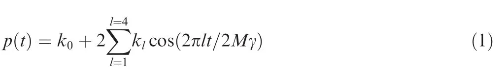
where γ is the digital filter tap coefficient,2Mis the length of a code element,k0andklare the weight coefficients offilter.The modulated signal isXtrans(t),which is written as follows:
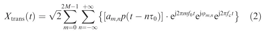
where τ0=and φ2m,2n+1= φ2m+1,2n= π/2.f0is the sub-carrier frequency,andfcis the carrier frequency.
The demodulated signal at the receiver is^cm,n,which is shown as

where Real{}represent the real part of the function,Xreceive(t)is the received signal.
2.2.Doppler effect from inter-satellite link
The inter-satellite link is the connection between two satellites.The orbit of a satellite can be described by the distance,the azimuth angle,and the elevation angle.14–16The distance between the two satellites are regular with the change of time.The relative velocity between the satellites can be predicted.The received signal is subject to the Doppler effect,as shown in Eq.(4).Assume the relative speedv(t)is a function of time.Although sometimes a satellite may deviate from its orbit,orbit parameters can be corrected periodically based on the navigation system.

whereCis the velocity of light.
The frequency of the received signal is changed with the Doppler effect.The Doppler shiftfdupis also affected by the carrier frequencyfcas shown in Eq.(5).The received signal is described by the dotted lines in Fig.3,whenfdup=0.1f0.It can be observed that each subcarrier has the same amount offrequency shift compared to the no-Doppler frequency shift signals(solid lines).On the ground,the Doppler effect mainly comes fromfc,becausefc?f0.
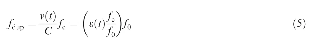

Fig.3 FBMC signal as fdup=0.1f0.
where ε(t)is the coefficient offrequency offsets.For the sake of convenience in writing, ε(t)is abbreviated as ε.
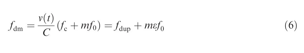
The Doppler frequency shiftfdmof a subcarrier is shown in Eq.(6).It includesfdupandmεf0,and each of them is caused by the carrier frequency shift and the subcarrier frequency interval differences.mε is the coefficient of sucarrier frequency deviation andmis ordinal number of sucarrier.In this paper,the Doppler scaling problem mainly comes from the subcarrier interval,sincefdupis eliminated in advance.The highest subcarrier frequency offset of the FBMC signals is described by the dotted lines in Fig.4,whenmmaxε=0.1.It can be observed that the frequency shift of a subcarrier is gradually increasing,compared with the original signals(solid lines).
2.3.Analysis of Doppler scaling in inter-satellite link
The impact of the Doppler scaling is analyzed in this subsection.The FBMC signal at the receiver is expressed as
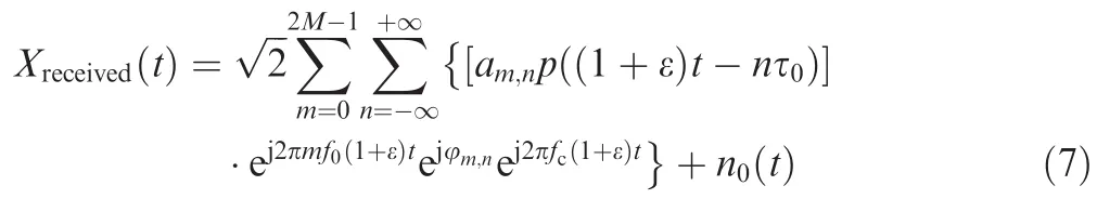
The demodulated signal can be expressed as


Fig.4 FBMC signal as mmaxε=0.1.
wherey^α,yI,and^n0are the useful signal,the interference from other signals,and the channel noise,17,18respectively.lt,ε are the time and frequency offsets,respectively.
The signal to interference and noise ratio(SINR)is represented as
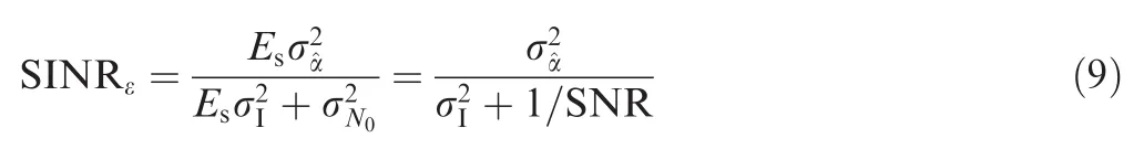
whereEsis the power of the signal,whileresent the variances ofy^α,yI,and^n0,respectively.
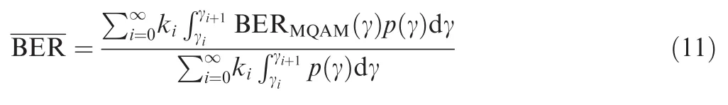
In this paper,the multiple quadrature amplitude modulation(MQAM)technique is used in subcarrier modulation.19,20The bit error rate(BER)of a subcarrier and that of the multicarrier system are described in Eqs.(10)and(11),respectively.
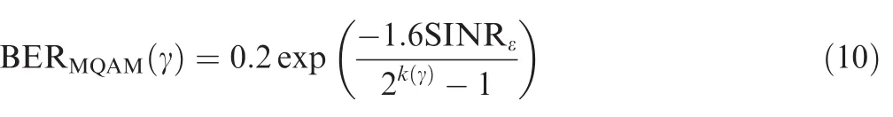
wherek(γ)is the order of MQAM.
3.Proposed method of eliminating Doppler scaling
3.1.Doppler-FFT description
This paper proposes a Doppler-FFT algorithm to solve the impact of the Doppler scaling.The elementary structure of the Doppler-FFT is expressed in Fig.5.The Doppler-FFT has a butterfly structure similar to that of the traditional FFT,yet the frequency interval of the Doppler-FFT is increased to(1+ε)times compared to that of the traditional one.This improvement adjusts the frequency of each subcarrier fromfto(1+ε)f,and thus the effect of the Doppler scaling can be counteracted by this man-made frequency offset.The following section will discuss the Doppler-FFT algorithm.
The traditional FFT of the uniform subcarrier interval is described in Eq.(12),Skis The signal to be processed.In this paper,the demodulation process should be changed to Eq.(13)to solve the Doppler scaling.Compared with the uniform modulation FFT,exp[-j2π(1/T)t]turns into exp{-j2π[(1+ ε)/T)]t}.Meanwhile,X(k)is divided into two groups by the parity ofn,which is represented by Eq.(14).
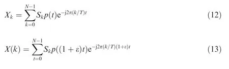

Fig.5 N/2-Doppler-FFT structure.
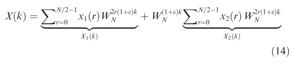
wherer=0,1,...,N/2-1;=exp(-j2πa/b).
To a higher level of decomposition,X(k)is divided into four groups,as shown in Eq.(15).SimplifyX1(N/2+k),X2(N/2+k),andrespectively for Eqs.(16),(17),and(18).Then,Eq.(15)is replaced by Eq.(19).
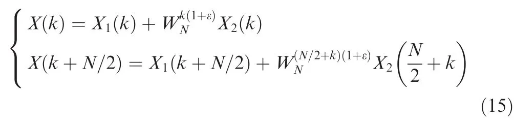
wherek=0,1,...,N/2-1.
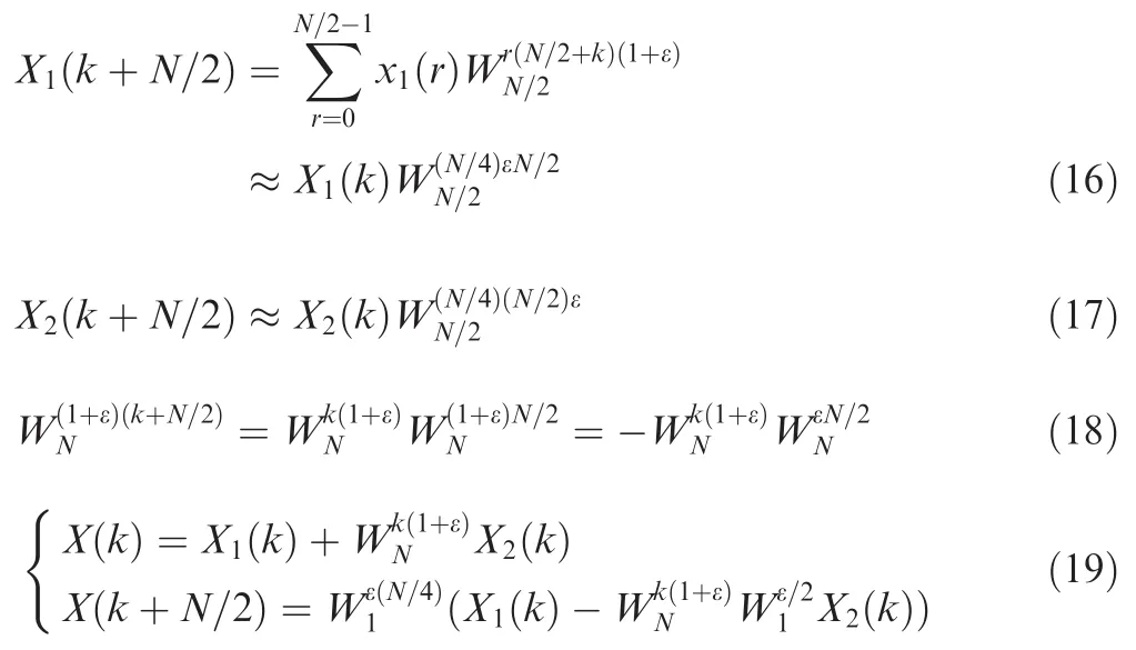
wherek=0,1,...,N/2-1,andthe multiplication factors,respectively.
According to the proof above,the butterfly operation structure is shown in Fig.5.The Doppler scaling can be eliminated by these precautions.
To a higher level of decomposition,asN=2M,N/2=2M-1is even,and twoN/2-Doppler-FFT can also be further decomposed into fourN/4-Doppler-FFT.Fig.6 shows the structure of theN/8-Doppler-FFT.In theN/8-Doppler-FFT structure,three-level butterfly transformations are represented by three kinds of colors.
3.2.Eliminating Doppler scaling in satellite communications
This paper gives a solution to eliminate the Doppler scaling in satellite communications.As shown in Fig.7,the input symbols are mapped into the constellation diagram,and then the time domain waveform is generated through the IFFT.After that,the standard FBMC signal,as shown in Eq.(20),is shaped by the filter,and then is transmitted through the satellite channel.Due to the Doppler scaling in the transmission,the spectrum intervals between the subcarriers are changed.After pulse shaping by the filter,the Doppler-FFT is used to eliminate the Doppler scaling.The estimates of Doppler scaling factors^ε(t)are stored in the factor memory,which are the input parameters during the Doppler-FFT.
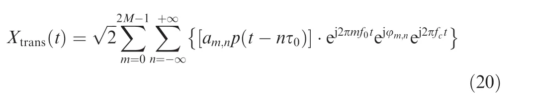
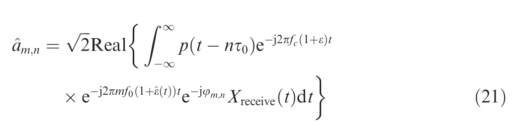
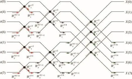
Fig.6 N/8-Doppler-FFT structure.
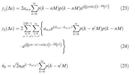
In this article,ε is received from predetermined orbit parameters.There is an estimation error Δε between the predictions^ε(t)and the actual values ε,due to the orbital perturbation.The effect of the estimation error is analyzed below.The demodulated signal can be expressed as

wherey^α(Δε),yI(Δε),and^n0are the useful signal,the interference from other signals,and the channel noise,respectively.y^α(Δε)andyI(Δε)are two functions which change with Δε,such as Eqs.(23),(24),and(25).
The bit error rate of the designed system is affected by the estimation error Δε as follows:
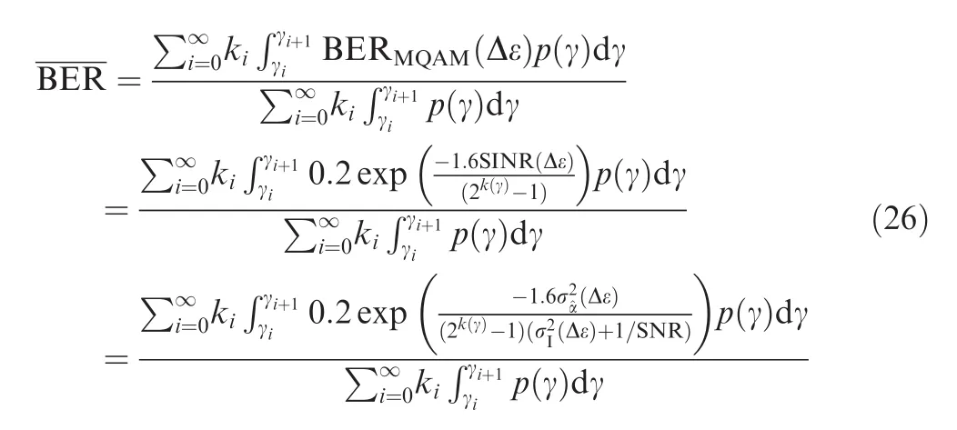
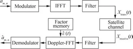
Fig.7 Structure of the new method to eliminate the Doppler scaling.
Nevertheless,with a decrease of the estimation error Δε,the interference can be eliminated.By using the Doppler-FFT algorithm,the FBMC demodulator achieves the desired effect.
4.Simulation and analysis
4.1.Simulation of Doppler scaling
We have established a satellite system model by satellite tool kit(STK).Two LEO satellites are created for the simulation.The altitude is set to 781 km,the orbital angle is set to 30°,and the time precision is set to one second.The distance between the satellite changes and the relative speed between the two satellites are shown in Figs.8 and 9,respectively.Fig.9 shows that the relative speed between the LEO satellites can reach 3500 m/s.The Doppler factor ε is 1.167 × 10⁻⁵.The subcarrier number is set to 1024,and the Doppler frequency shift of subcarriers in the satellite communication can reach up to 1.2%f0.Considering a satellite may deviate from the orbit,we correct orbit parameters at a fixed period through a navigation system.Because of the discretization error and the trajectory prediction errors,the real value of the Doppler factor is ε× (1± Δε).The relative speed of communication terminals is generally no more than 30 m/s on the ground,and the Doppler frequency shift can reach up to 0.01%f0.

Fig.8 Parameters of the inter-satellite link(the time is 2015 November 18–19).
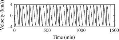
Fig.9 Velocity between the satellites.
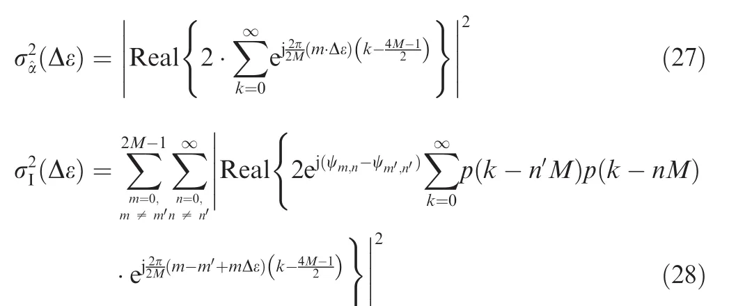
The useful energy of the demodulation signal is represented byand it is a function of time and frequency offset.The loss energy(1-is shown in Fig.10,and it can be seen that the useful energy changes slightly.The total energy of the ICI and the ISI is represented asIt is also a function of time and frequency offset.ltrepresents the time offsets.The interference energy is shown in Fig.11.Whenmmaxε=1%,=0.016,which significantly reduces the performance of the system.The curves in Fig.12 describe the theoretical BER performances when the Doppler scalingmmaxε is 0,0.01%,and 1.2%,respectively.According to the analysis above,the Doppler scaling on the ground is no more than 0.01%,and 1.2%is a reasonable value for the Doppler scaling factor in the LEO satellite communication.It can be seen that the impact is ignorable in the terrestrial communication,while rather significant in the satellite communication.
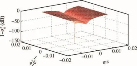
Fig.10 Loss-energy of the useful signal.
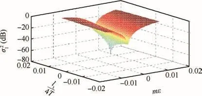
Fig.11 Energy of the interference signal.
4.2.Performance of eliminating Doppler scaling in satellite communications
4.2.1.Spectral analysis of Doppler-FFT algorithm
We use the frequency spectrum analysis to validate the performance of the Doppler-FFT.Fig.13 shows the comparison of spectra when the Doppler scaling factormmaxε is 0 and 1.2%.Compared to the no-Doppler signal,the spectrum of the signal withmmaxε=1.2%shifts to the right obviously when using the traditional FFT,whereas changes slightly when using the Doppler-FFT.Thus,the problem of the Doppler scaling can be resolved by the Doppler-FFT.
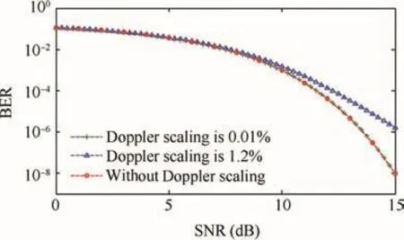
Fig.12 Theoretical BER when the Doppler scaling factor mmaxε is 0,0.01%,and 1.2%.
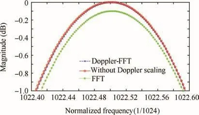
Fig.13 Spectrum comparison between different spectral analysis methods when the frequency offset mmaxε=1.2%.
4.2.2.Effect of estimation errors
The proposed method in this paper is based on an accurate estimation of the Doppler scaling.However,the estimation errors Δε are unavoidable.This paper analyzes the energy loss caused by the estimation errors Δε in this subsection.According to Eqs.(24)and(25),we know that the loss energy of the useful signal and the energy of the interference signal increase with the estimation errors Δε.Fig.14 confirms the above conclusion and presents the detailed data.
Upon further analysis,the SINR is also reduced compared to the SNR.It can be seen from Fig.15 that the change of the SINR is negligible when the estimation errors Δε are within 10%.
4.2.3.In fluence on different parameters of FBMC signals
Fig.15 are the SINR values which are adopted by three prototype filters,including PHYDYAS,RRC,IOTA.Fig.15 shows the relationship between the SINR and the SNR with three different kinds of prototype filter respectively.It can be observed that the SINR almost has no degradation for arbitrary types of filters as long as Δε are within 10%.
Fig.16 shows the impact of the number of subcarriers on the SINR.Simulation shows that the SINR decreases as the number of subcarriers increases,agreeing well with the fact that the Doppler scaling increases with the number of subcarriers.Fig.16 also shows that the Doppler scaling can always be well eliminated by using the Doppler-FFT for a common number of subcarriers.
4.2.4.The performance of Doppler-FFT compared with NUFFTIn this subsection,we compare the proposed algorithm to the NUFFT10in the frequency domain.The subcarrier number is 128,and the Doppler scalingmmaxε is 0.5.Fig.17(a)shows the frequency domain of the transmitted signal(blue),while Fig.17(b)shows the frequency domain of the received signal.It can be seen that subcarriers with higher subcarrier indices have obviously misaligned with those in the transmitted signal.This is due to the frequency-dependent shifts in the Doppler scaling.To eliminate the impact of the Doppler scaling,we correct the received signal using the Doppler-FFT.Fig.17(c)shows that the Doppler scaling corrected signal has subcarrier peaks aligned with those in the transmitted signal,which has the same excellent performance as that of the NUFFT in Ref.10.
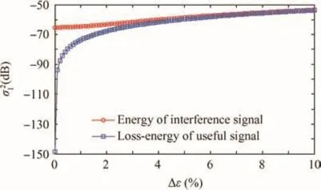
Fig.14 Energy losses with different estimation errors Δε.
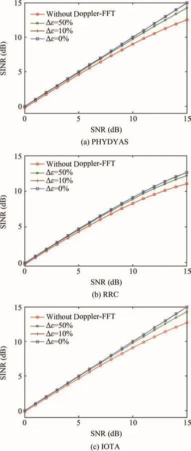
Fig.15 SINR with different estimation errors Δε.
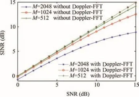
Fig.16 SINR with different sub-carrier numbers.
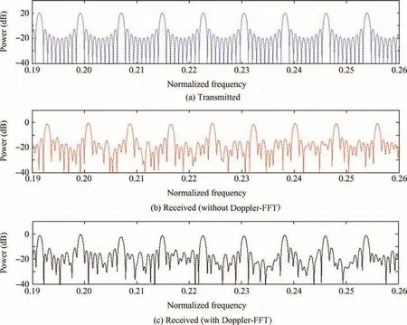
Fig.17 Preamble parts of the transmitted signal and the received signal before Doppler scaling correction using the Doppler-FFT.
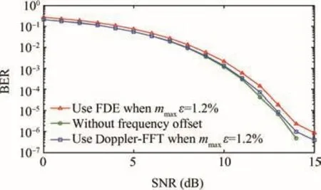
Fig.18 Performance comparison between different methods.
The complexity of the Doppler-FFT iso(Nlog2N),which has the same order of the traditional FFT.As that of the NUFFT iso(Nlog2(1/χ)),where χ is a figure indicating the accuracy of the interpolation process,10the Doppler-FFT algorithm can achieve the same performance but with lower complexity and more powerful usability than those of the NUFFT.
4.2.5.BER performance in satellite communications
In order to verify the effect of the Doppler-FFT,a comparison experiment is simulated between the new method and some existing methods.The FDE algorithm is selected as an example of existing methods,which essentially uses a tunable filter coefficient to compensate the frequency characteristics of signals.The received data from all receiving antennas on one frequency tone is considered jointly,and then the minimum mean square error(MMSE)equalization is implemented.Then the transmission system achieves the objectives of the undistorted.In the simulation,the Doppler scalingmmaxε is 1.2%f0,and the error ofmmaxε is 1%from estimation.Through the comparison experiment,it can be found that the Doppler-FFT has a performance gain of about 0.4 dB compared to the FDE,when the subcarrier frequency offset is 1.2%f0(see Fig.18).Therefore,the proposed method has a better performance than that of the FDE algorithm.
5.Conclusion
In this paper,we have proposed a Doppler-FFT algorithm to solve the Doppler scaling problem in satellite communications.Firstly,we analyze the impact of the Doppler scaling to an FBMC signal in inter-satellite link channels.Then,the butterfly structure of the Doppler-FFT is presented.In addition,a the oretical proof is also provided.Finally,simulation results have verified our analysis that the impact of the Doppler scaling can be completely eliminated by using the Doppler-FFT.Moreover,the complexity is of the same order as that of the traditional FFT algorithm.In conclusion,the proposed method is effective in satellite communications.
Acknowledgements
This study was supported by the National Natural Science Foundation of China(No.91438116),by the Program for New Century Excellent Talents in University of China(No.NCET-12-0030),by the National Hi-Tech Ramp;D Program of China(No.2015AA7014065),and by the Shanghai Aerospace Science and Technology Innovation Fund (No.SAST2015089).
1.Dommel JO,Boccolini GA,Raschkowski LE,Jaeckel ST,Thiele LA,Haustein TH,et al.5G in space:PHY-layer design for satellite communications using non-orthogonal multi-carrier transmission.Proceedings of 7th advanced satellite multimedia systems conference and the 13th signal processing for space communications workshop(ASMS/SPSC);2014 Sept 8–10;Livorno.Piscataway(NJ):IEEE Press;2014.p.190–6.
2.Wunder GE,Kasparick MA,Wild TH,Schaich FR,Chen YE,Dryjanski MA,et al.5GNOW:Non-orthogonal,asynchronous waveforms for future mobile applications.IEEE Commun Mag2014;52(2):97–105.
3.Dimitrov SV,Privitera NI,Suffritti RO,Boccolini GA,Awoseyila AD,Evans BA.Spectrally efficient waveforms for the return link in satellite communication systems.Proceedings of 2015 European conference on networks and communications(EuCNC);2015 June 29–2015 July 2;Oulu.Piscataway(NJ):IEEE Press;2015.p.6–10.
4.Siohan PI,Siclet CY,Lacaille NI.Analysis and design of OFDM/OQAM systems based on filterbank theory.IEEE Trans Signal Process2002;50(5):1170–83.
5.Wei LE,Schlegel CH.Requirements of timing and frequency synchronizations for multi-user OFDM on satellite mobile channel.Proceedings of global telecommunications conference(GLOBECOM);1994 Nov 28–Dec 2;San Francisco.Piscataway(NJ):IEEE Press;1994.p.735–9.
6.Thomas NA,Boucheret ML,Ho AT,Dervin MA,Deplancq XA.OFDM receiver for fixed satellite channel.J Commun netw2010;12(6):533–43.
7.Van JJ,Sandell M,Borjesson PO.ML estimation of time and frequency offset in OFDM systems.IEEE Trans Signal Process1997;45(7):1800–5.
8.Huang DE,Letaief KB.An interference cancellation scheme for carrier frequency offsets correction in OFDMA systems.IEEE Trans Commun2005;53(7):1155–65.
9.Guan QY,Zhao HL,Guo QI.Cancellation for frequency offset in OFDM system based on TF-LMS algorithm.J Cent South U T2010;17(6):1293–9.
10.Yuen CH,Farhang BE.Doppler scaling correction in OFDM.Proceedings of 2013 international conference on communications(ICC);2013 June 9–13;Dresden.Piscataway(NJ):IEEE Press;2013.p.4713–7.
11.Aminjavaheri AM,RezazadehReyhani AH,Farhang-Boroujeny BE.Frequency spreading Doppler scaling compensation in underwater acoustic multicarrier communications.Proceedings of 2015 international conference on communications(ICC);2015 June 8–12;London.Piscataway(NJ):IEEE Press;2015.p.2774–9.
12.Chen YA,Zou LI,Zhao AN,Yin JN.Null subcarriers based Doppler scale estimation for multicarrier communication over underwater acoustic non-uniform Doppler shift channels.Proceedings of 2016 China ocean acoustics(COA);2016 Jan 9–11;Harbin.Piscataway(NJ):IEEE Press;2016.p.1–6.
13.Bregovic RO,Saramaki TA.A systematic technique for designing linear-phaseFIR prototypefiltersfor perfect-reconstruction cosine-modulated and modified DFT filterbanks.IEEE Trans Signal Process2005;53(8):3193–201.
14.Keller HA,Salzwedel HO,Schorcht GU,Zerbe VO.Geometric aspects of polar and near polar circular orbits for the use of intersatellite links for global communication.Proceedings of 48th vehicular technology conference(VTC);1998 May 21–21;Ottawa.Piscataway(NJ):IEEE Press;1998.p.199–203.
15.Wang ZY,Li JL,Qing GO,Gu XM.Analysis on connectivity of inter-orbit-links in a MEO/LEO double-layer satellite network.Chin J Aeronaut2006;19(4):340–5.
16.LeeSA,MortariDA.Design of constellations for earth observation with intersatellite links.J Guid Control Dynam2016;12(1):1–9.
17.Sriyananda MG,Rajatheva NA.Analysis of self-interference in a basic FBMC system.Proceedings of 78th vehicular technology conference(VTC);2013 Sep 2–5;Las Vegas.Piscataway(NJ):IEEE Press;2013.p.1–5.
18.Razavi R,Xiao P,Tafazolli R.Information theoretic analysis of OFDM/OQAM with utilized intrinsic interference.IEEE Signal Process2015;22(5):618–22.
19.Chung ST,Goldsmith AJ.Degrees offreedom in adaptive modulation:a unified view.IEEE Trans Commun2001;49(9):1561–71.
20.Dong ZC,Fan PZ,Lei XF.Power and rate adaptation based on CSI and velocity variation for OFDM systems under doubly selective fading channels.IEEE Access2016;4(1):6833–45.
3 June 2016;revised 21 September 2016;accepted 21 January 2017
Available online 14 June 2017
*Corresponding author.
E-mail address:rongke_liu@buaa.edu.cn(R.LIU).
Peer review under responsibility of Editorial Committee of CJA.
Production and hosting by Elsevier
http://dx.doi.org/10.1016/j.cja.2017.04.010
1000-9361?2017 Chinese Society of Aeronautics and Astronautics.Production and hosting by Elsevier Ltd.
This is an open access article under the CC BY-NC-ND license(http://creativecommons.org/licenses/by-nc-nd/4.0/).
Doppler effect;
Fast Fourier transforms;
Filter bank multi-carrier;
Inter-carrier interference;
Inter-symbol interference;
Signal to interference and noise ratio
 CHINESE JOURNAL OF AERONAUTICS2017年4期
- CHINESE JOURNAL OF AERONAUTICS的其它文章
- Guide for Authors
- Simulation and experimental investigation on a dynamic lateral flow mode in trepanning electrochemical machining
- Investigation of high-speed abrasion behavior of an abradable seal rubber in aero-engine fan application
- Dynamic performance of a C/C composite finger seal in a tilting mode
- A unifying approach in simulating the shot peening process using a 3D random representative volume finite element model
- Approach and landing guidance design for reusable launch vehicle using multiple sliding surfaces technique