
Thermal Magni fi er and Mini fier?
2016-05-14 12:51:11XiangYingShen沈翔瀛YiXuanChen陳祎璇andJiPingHuang黃吉平
Xiang-Ying Shen(沈翔瀛), Yi-Xuan Chen(陳祎璇),and Ji-Ping Huang(黃吉平)
Department of Physics,State Key Laboratory of Surface Physics,Key Laboratory of Micro and Nano Photonic Structures(Ministry of Education),and Collaborative Innovation Center of Advanced Microstructures,Fudan University,Shanghai 200433,China
1 Introduction
In order to control heat flux at will,Fan et al.[1]extended transformation mapping theory[2?3]to the domain of thermal conduction in 2008.Since the Laplace equation remains form invariance under linear coordinate transformation,a thermal cloak for steady state heat flow can be designed as a ring structure and has anisotropic and inhomogeneous thermal conductivity.One original intention of such types of thermal metamaterials is to hide an object inside the cloaking region without disturbing the external temperature pro file,which is so called the cloaking effect.In 2012,this cloaking effect has been experimentally achieved by using forty alternating layers of two different homogenous and isotropic materials.[4]This work has brought a promising prospect for practical applications of thermal metamaterials.Meanwhile,some theoretical scholars also proposed more simplified methods to realize the cloaking effect by adopting reduced parameters,[5]and other theoretical[6?7]or experimental[4,8?10]research groups extended the transformation mapping theory to the domain of unsteady state heat flow(for which T is dependent on the time t).In a word,using transformation mapping theory to design thermal metamaterials with novelty characteristic has attracted a lot of attentions in the science community.[1,4?8,11?19]

Fig.1 (Color online)Schematic graph shows how a thermal illusion device works.(a)shows the temperature distribution of a soldier.(b)depicts the temperature distribution of a tree.In(c)the illusion device changes the temperature distribution and makes a soldier“seem”like a tree.
Recently,inspired by optics illusion,thermal illusion devices were also put forward.[20?22]Figure 1 shows the mechanism of such a device.If the temperature is the only signature,a distorted distribution of temperature may mislead people detecting the appearance of an object.In recent papers,some new types of thermal cloaks permit the cloaked object to share the temperature gradient again by using complementary materials.[23?24]As a result,the object inside the cloak can feel the external heat flow.However,the design requires that the thermal conductivities of the complementary layers must be negative.[1,25?27]In principle,without violating the second law of thermodynamics,to realize such negative values one should apply external work to the system appropriately(say,the application of the refrigerator).
In this article,we will report a new thermal illusion device,which consists of a cloak layer and a complementary layer.This design can distort the temperature signatures,and lead to an illusion that the object inside seems zoomed out or in.In other words,we design a thermal metamaterial to hide the original object and let it reappear in another size.For conduction process,we can figure out the object’s size by detecting the temperature distribution around it.According to the simulations,the device can help to change the temperature distribution and make the object appear to be bigger or smaller.Moreover,people can achieve these dual purposes of magnification and minification in one device just by changing the external work.We shall also offer some suggestions on how to construct the device.
2 Theoretical Model and Design Method
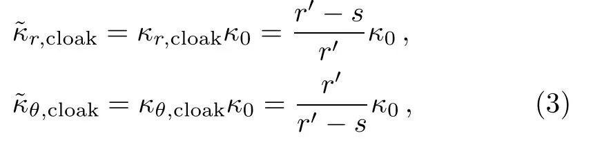
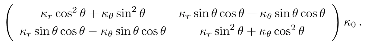
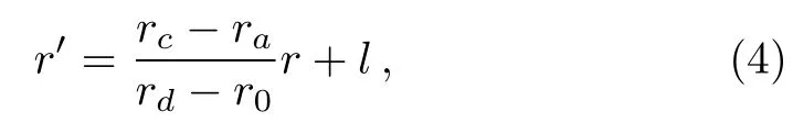
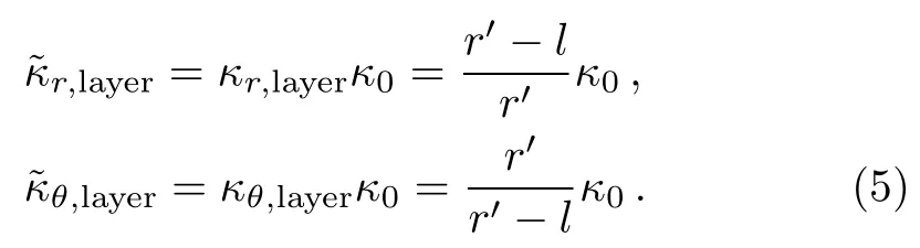
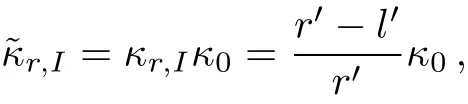
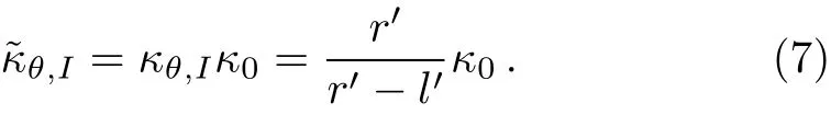
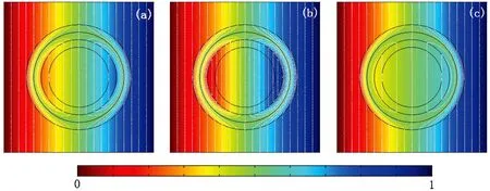
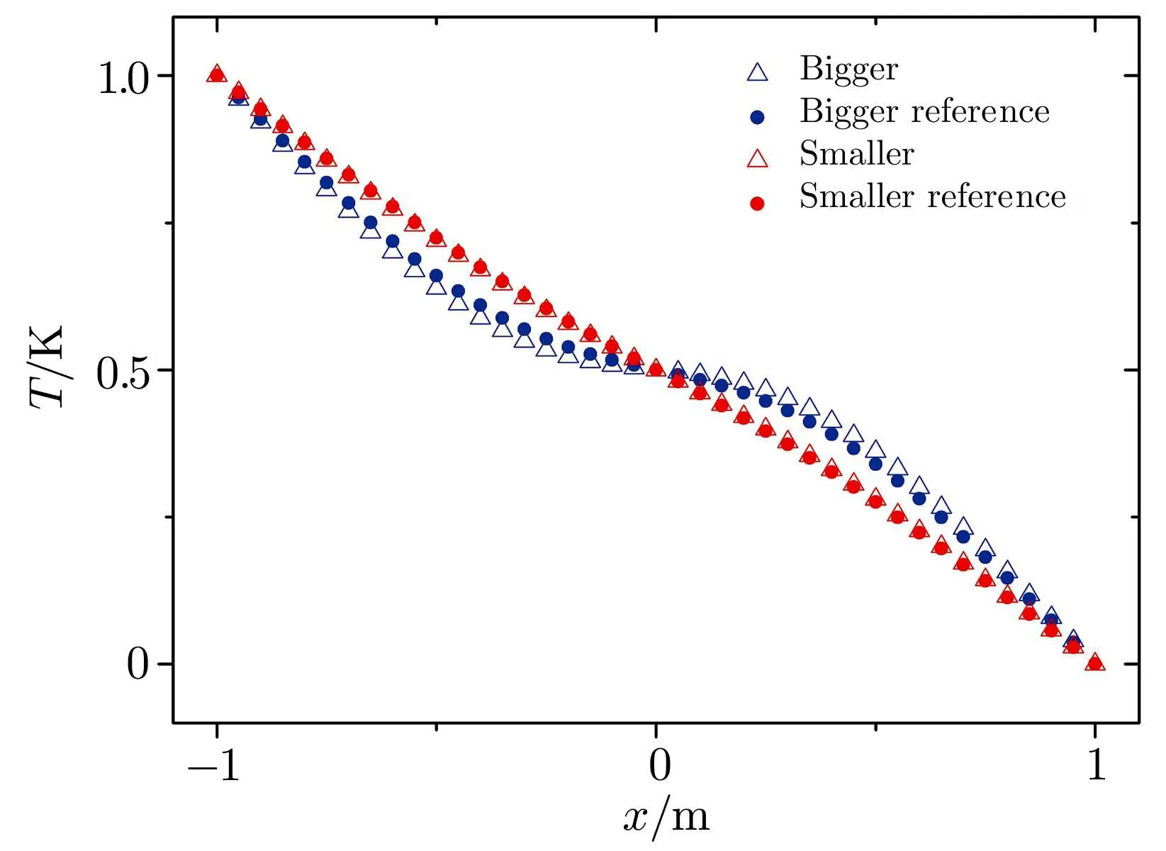
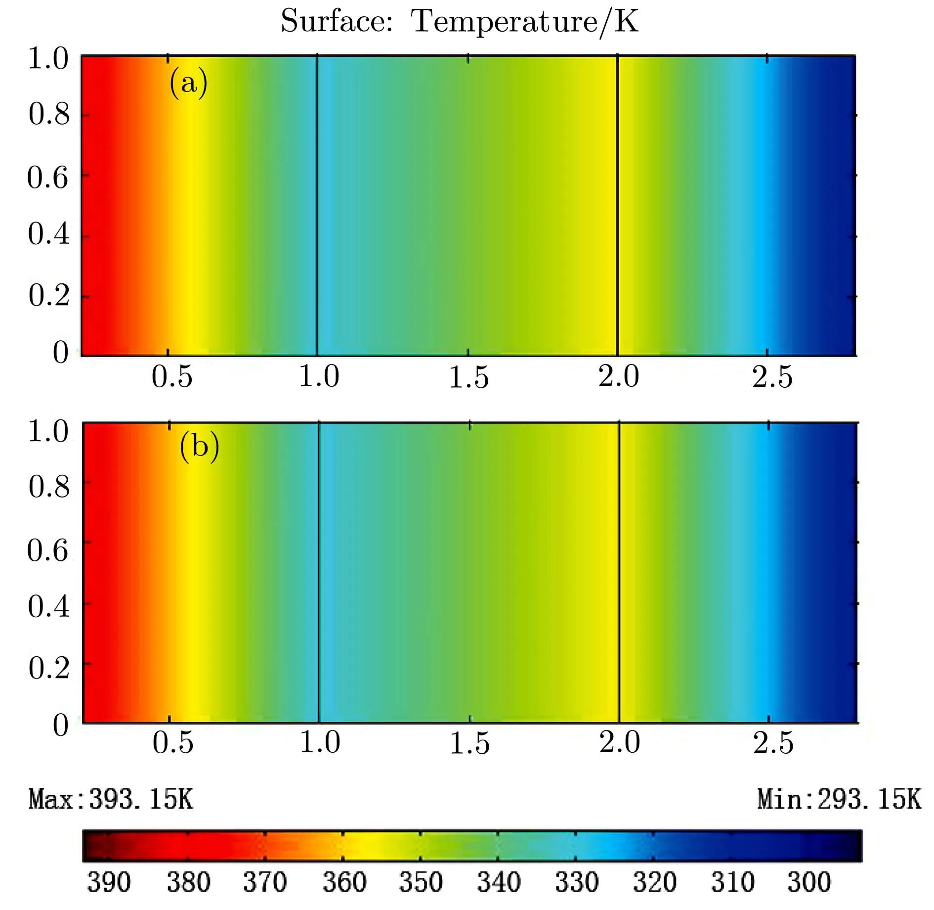
In Fig.2,we give the schematic graph of the illusion device so called the thermal magnifier or minifier,which has a two-layers structure.Without loss of generality,consider the case of steady state heat flow in a two-dimensional system with polar coordinates(r,θ)and the heat source is absent.Here r and θ represent the radial and angular coordinate respectively.The heat conduction equation can be expressed as:?·?κ?T=0,where?κ denotes a thermal conductivity and T represents temperature distribution at each point in the space.A non-perfect thermal cloak effect can be achieved when we compress the annulus region with r0 where s=rb(ra?r0)/(rb?r0)and r′is the radial coordinate in the transformed coordinates.In this transformation,we make the “invisible region” (r Fig.2 (Color online)Schematic graph shows a cloak and a complementary layer:the cloak is located within the region of radius r satisfying ra In the distorted coordinates,this transformation method(Eq.(1))yields a new thermal conductivity tensor,which can be derived and described by′(thermal conductivity in the distorted coordinates)and(thermal conductivity in the original coordinates), where J is the Jacobian matrix corresponding to the transformation,JTdenotes the transposed matrix of J,and determinant of J is represented by det(J).Thus,the cloaking parameters(the radial and angular conductivities,r,cloakandθ,cloak)can be expressed as where κ0is the thermal conductivity of the background.In addition,the expression of the new transformation thermal conductivity in two-dimensional cartesian coordinate system would be written as Essentially,the cloaking transformation is a compression transformation,and it leads to a thermal illusion that a bigger annulus seems like a smaller one. Now,considering the complementary layer in the device.This layer permits the heat flux flowing through the invisible region(r where l=(rard?rcr0)/(rd?r0)and rdis the radius of the object.Then,we can obtain the complementary layer’s parameters(i.e.,the radial and angular thermal conductivities,r,layerandθ,layer)for the complementary layer(rc Obviously,the determinant of the conductivities of cloak and complementary layers both equal to κ0,which grants the region within rb>r>rdcan be regarded as the background even after the transformation.According to Eq.(5),it should be noted the parameters of the complementary layer(rc As shown in Fig.2,this mapping(Eq.(4))transforms the region of r0 where l′=(ra?rcr0)/(?r0)and as discussed above,is the diameter for the illusionary image.Therefore,the components of the conductivity tensor can be derived as It should be noted according to the transformation the illusionary image size exactly equals to r′dwithout any other requirements.If r′d>rd,the device works like a magnifier and the reappearing object is larger than the original one;if r′d Fig.3 (Color online)(a) κr,cloakand κθ,cloakas a function of r;(b) κr,layerand κθ,layeras a function of r.The parameters are set as r0=0.05 m,ra=0.6 m,rb=0.7 m,rc=0.5 m,and rd=0.4 m. In order to show the effect of our device,we perform finite element simulations based on the commercial software COMSOL Multiphysics.[28]As demonstrated in Fig.2,an object,whose radius is rd,is placed in the central region of the cartesian system(X,Y).The cloak layer and the complementary layer are located in the region of ra Fig.4 Simulation results of temperature distribution are denoted by rainbow color surface.The background thermal conductivity is κ0.A circular object with the same thermal conductivity κ0is situated in the center of the device,whose radius is rd.(a)The temperature distribution ofrd=0.4 m;(b)The temperature distribution of magnifier case>rdand =0.7 m;(c)The temperature distribution of minifier case Fig.5 (Color online)(a),(c),and(e)use the same parametersas in Figs.4(a)–4(c)respectively,but the object is replaced with a better thermal conductor of thermal conductivity 400 W/(m·K).(b),(d),and(f)are reference groups;they show the temperature distribution of a material with the same thermal conductivity but different radiusPeople will be cheated by the thermal illusion device and give wrong judgements on the object’s size. In Figs.4(a)–4(c),the object inside the device has the same thermal conductivity as the background and from Fig.4(a)to Fig.4(c)the r′dis 0.4 m(same as the original size of the object),0.7 m and 0.3 m respectively.For a magnifier case in Fig.4(b),we should note that the temperature inside the device decreases more rapidly than the reference in Fig.4(a),while for a minifier case in Fig.4(c)the temperature gradient is less than Fig.4(b).A more explicit case is shown in Fig.5,where the parameter r′dset in Figs.5(a),5(c),5(e)are same as the values adopted in Figs.5(a)–5(c)respectively,but the object was replaced with a better thermal conductor with thermal conductivity 400 W/(m·K);Figs.5(b),5(d),5(f)are the reference group,which is used to demonstrate the temperature distribution caused by the real objects with different diameters 0.4 m,0.7 m and 0.3 m.It should be noted that the device creates a thermal illusion that makes the object seems to be bigger or smaller than the original one.From the temperature distribution,people will be cheated by the illusion and misjudge the size of the object inside.To show the simulation results more precisely we give Fig.6,which presents the performances of magnifier and minifier shown in Fig.5(c)and Fig.5(e)by adopting the X-dependent temperature data(T)along Y=0.Obviously,the device works. Fig.6 (Color online)X-dependent temperature(T)along Y=0 in Figs.5(c)–5(f). Fig.7 (a)Temperature distribution of a square material with a negative thermal conductivity;(b)Temperature distribution of a square material with an effective negative thermal conductivity.For plotting the figures,in(a),the conductivity of the square material and background are set to be ?100 W/(m·K)and 40 W/(m·K)respectively.In(b)the square material is with a conductivity of 100 W/(m·K)and we show the same pattern of temperature distribution by applying external work to keep the temperature constant on the boundaries of X=1 m and X=2 m. The characteristics of this device is that you are able to decide it as a magnifier or a minifier by changing the parameters r′d.The device consists of two parts:cloak layer and complementary layer with negative thermal conductivity.For a thermal cloak layer,we can fabricate it by using an alternation of two homogeneous isotropic layers of thicknesses dAand dBand conductivities κAand κB.We derive the following effective parameters by utilizing the effective medium theory:[4,6,29] where η=dB/dA,and the thicknesses of layers A and B have relation that dA+dB=1.Since the complementary layer shares the same pattern of transformation mapping with cloak layer,it could be manufactured in the same method.However,the problem is the negative thermal conductivity.Fortunately,an effective negative thermal conductivity can be achieved by applying external work without violating the second law of thermodynamics.Here,we present a simple case to show how to create a homogeneous isotropic layer with a negative thermal conductivity.Figure 7(a)shows the temperature distribution of a square material with a negative thermal conductivity of ?100 W/(m·K)settled in a host medium with conductivity of 40 W/(m·K).To achieve the same effect,in Fig.7(b),we keep the temperature constant on the boundaries of X=1 m and X=2 m,which means appropriate external work must be applied to the system.The exact values of the temperatures on the boundaries can be figured out by considering the continuity conditions,say So if we change the external work applied to the complementary layer,the parameter r′dwould change.Therefore,this thermal magnifier and minifier can be controlled as we desire. We have used transformation mapping theory to design a different kind of thermal meta-materials.A feature of such device is to create a thermal illusion that the object inside the device appears itself in a different size.The feature also permits people to decide to magnify or minify the size of object through controlling the external work applied to the system.The underlying mechanism originates from the complementary effect of the additional complementary materials.This work provides a way to design new thermal devices,where heat conduction can be controlled at will,by using complementary materials tailored according to thermal transformation theory. References [1]C.Z.Fan,Y.Gao,and J.P.Huang,Appl.Phys.Lett.92(2008)251907. [2]J.B.Pendry,D.Schurig,and D.R.Smith,Science 312(2006)1780. [3]U.Leonhardt,Science 312(2006)1777. [4]S.Narayana and Y.Sato,Phys.Rev.Lett.108(2012)214303. [5]T.C.Han,T.Yuan,B.W.Li,and W.C.Qiu,Sci.Rep.3(2013)1593. [6]S.Guenneau,C.Amra,and D.Veynante,Opt.Express 20(2012)8207. [7]J.Y.Li,Y.Gao,and J.Huang,J.Appl.Phys.108(2010)074504. [8]R.Schittny,M.Kadic,S.Guenneau,and M.Wegener,Phys.Rev.Lett.110(2013)195901. [9]T.C.Han,X.Bai,D.Gao,John T.L.Thong,B.W.Li,and C.W.Qiu,Phys.Rev.Lett.112(2014)054302. [10]H.Xu,X.Shi,F.Gao,H.Sun,and B.L.Zhang,Phys.Rev.Lett.111(2014)054301. [11]S.Narayana,S.Savo,and Y.Sato,Appl.Phys.Lett.102(2013)201904. [12]Y.G.Ma,L.Lan,W.Jiang,F.Sun,and S.L.He,NPG Asia Mater.5(2013)e73. [13]E.M.Dede,T.Nomura,P.Schmalenberg,and J.S.Lee,Appl.Phys.Lett.103(2013)063501. [14]T.Z.Yang,L.J.Huang,F.Chen,and W.K.Xu,Appl.Phys.Lett.46(2013)305102. [15]X.He and L.Z.Wu,Appl.Phys.Lett.102(2013)211912. [16]G.X.Yu,Y.F.Lin,G.Q.Zhang,Z.Yu,L.L.Yu,and J.Su,Front.Phys.6(2011)70. [17]Y.G.Ma,Y.C.Liu,M.Raza,Y.D.Wang,and S.L.He,Phys.Rev.Lett.113(2014)205501. [18]Y.C.Liu,W.Jiang,S.L.He,and Y.G.Ma,Opt.Express 22(2014)170006 [19]D.M.Nguyen,H.Y.Xu,Y.M.Zhang,and B.L.Zhang,Appl.Phys.Lett.107(2015)121901 [20]Y.X.Chen,X.Y.Shen,and J.P.Huang,Euro.Phys.J.Appl.Phys.70(2015)20901 [21]N.Q.Zhu,X.Y.Shen,and J.P.Huang,AIP Adv.5(2015)053401. [22]T.C.Han,X.Bai,John T.L.Thong,B.W.Li,and C.W.Qiu,Adv.Mater.26(2014)1731. [23]X.Y.Shen and J.P.Huang,Int.J.Heat.Mass.Tran.78(2014)1. [24]Y.Gao and J.Huang,EPL 104(2013)44001. [25]A.A.Kovalev and Y.Tserkovnyak,EPL 97(2012)67002. [26]F.L.Bakker,A.Slachter,J.P.Adam,and B.J.van Wees,Phys.Rev.Lett.105(2010)136601. [27]A.Iacobucci,F.Legoll,S.Olla,and G.van Stoltz,Phys.Rev.E 84(2011)061108. [28]http://www.comsol.com/. [29]J.P.Huang and K.W.Yu,Phys.Rep.431(2006)87.


3 Results and Discussion


4 Conclusions
 Communications in Theoretical Physics2016年3期