
Dynamic modeling and simulation for the rigid flexible coupling system with a non-tip mass
2015-04-22 02:33:16LICuichun李崔春MENGXiuyun孟秀云LIUZaozhen劉藻珍
LI Cui-chun(李崔春), MENG Xiu-yun(孟秀云), LIU Zao-zhen(劉藻珍)
(Key Laboratory of Dynamic and Control of Flight Vehicle, Ministry of Education, Beijing Institute of Technology, Beijing 100081, China)
?
Dynamic modeling and simulation for the rigid flexible coupling system with a non-tip mass
LI Cui-chun(李崔春), MENG Xiu-yun(孟秀云), LIU Zao-zhen(劉藻珍)
(Key Laboratory of Dynamic and Control of Flight Vehicle, Ministry of Education, Beijing Institute of Technology, Beijing 100081, China)
The rigid flexible coupling system with a mass at non-tip position of the flexible beam is studied in this paper. Using the theory about mechanics problems in a non-inertial coordinate system, the dynamic equations of the rigid flexible coupling system with dynamic stiffening are established. It is clearly elucidated for the first time that, dynamic stiffening is produced by the coupling effect of the centrifugal inertial load distributed on the beam and the transverse vibration deformation of the beam. The modeling approach in this paper successfully solves problems of popular modeling methods nowadays: the derivation process is too complex by using only one dynamic principle; a clearly theoretical mechanism for dynamic stiffening can’t be offered. First, the mass at non-tip position is incorporated into the continuous dynamic equations of the system by use of the Dirac function and the Heaviside function. Then, based on the conclusions of orthogonalization about the normal constrained modes, the finite dimensional state space equations suitable for controller design are obtained. The numerical simulation results show that: dynamic stiffening is included in the first-order model established in this paper, which indicates the dynamic responses of the rigid flexible coupling system with large overall motion accurately. The results also show that the mass has a softening effect on the dynamic behavior of the flexible beam, and the effect would be more obvious when the mass has a larger mass, or lies closer to the tip of the beam.
non-inertial coordinate system; rigid flexible coupling; dynamic stiffening; mass at non-tip position; constrained mode
The rapid development of aerospace technology nowadays has made the structure of spacecraft become more and more complex. A new spacecraft is often equipped with large flexible appendages, on which there might be one or several function masses. Therefore, the control object changes from a traditional rigid body to a flexible multi-body system. The essence of the modeling of a flexible multi-body system is the study of a rigid flexible coupling dynamic problem. It is a new cross discipline closely related to classical dynamics, continuum mechanics, modern control theory, and computation technology[1].
In practical engineering, when the system is undergoing large overall motion, it is necessary to consider the significant impact generated by structural flexibility in motion. Even though the traditional zero-order model still has a large application field[2-3], the simulation results would be divergent because it can’t capture the dynamic stiffening term caused by large overall motion[4]. In 1987, Kane[5]analyzed a flexible beam with large overall motion, and pointed out that, if the dynamic responses of a cantilever beam with large rotating velocity were investigated by utilizing the zero-order approximate coupling model, the result would be divergent and inaccurate. Based on the conclusion above, Kane put forward the concept of dynamic stiffening. From then on, the dynamic stiffening problem was studied by many scholars, and a large number of approaches were proposed[6-9]. Based on the coupling of the elastic deformation and the large overall motion, the first-order approximate coupling model presented[9]not only considers the coupling of the small deformation of beam and the large overall motion, but also takes the coupling of the longitude deformation and the transverse deformation into account. So far, there is no real rational mechanism for dynamic stiffening in theory till now. The modeling of a rigid flexible coupling system with dynamic stiffening is still an important part of academic researches[10-15]. Meanwhile, the increasing complexity of aerospace tasks makes the flexible appendage with one or several functional masses, so the simple physical model (hub-beam) can’t meet the needs of modeling any longer. It becomes an important task that how to incorporate the mass into the dynamic model of a rigid flexible coupling system[16-18].
To sum up, there are two major problems lying in the modeling of a rigid flexible coupling system: ① the mass must be incorporated into the dynamic model of the system; ② the dynamic stiffening should be included in the dynamic behaviors of the model.To solve these problems, a physical model (hub-beam-mass) is studied in this paper. Applying the subsystem modeling principle, the dynamic equations of the system with dynamic stiffening are established via the theory about mechanics problems in a non-inertial coordinate system, material mechanics, angular momentum theory, and vector analyses. This paper provides a rational mechanism for dynamic stiffening in theory. Meanwhile, the mass is incorporated into the continuous dynamic equations of the system by use of the Dirac function and the Heaviside function. The impacts of the two properties (position and mass) of the mass on the dynamic responses of the rigid flexible coupling system are investigated comprehensively, and the decisive role of the mass playing on the boundary conditions of the constrained modes of beam is emphasized.
1 Continuous dynamic modeling based on mechanics problems ina non-inertial system
1.1 Rigid flexible coupling physical model
Consider the physical model of a rigid flexible coupling system as shown in Fig.1, which consists of a central rigid body (hub), a flexible beam (beam) and a mass at non-tip position of the beam (mass). Refer to Ref.[19], the ditterence between the two system is the mass on the beam.mtis the mass, anddis the position on beam for mass. Furthermore,dis in the interval [0, 1). It must be pointed out that, corresponding to the boundary conditions of the beam, the position of mass on the flexible beam is clearly restricted tod∈[0, 1) in this paper. That is to say, mass lies at any position of beam except the tip.
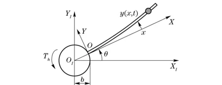
Fig.1 Physical model of a rigid flexible coupling system
1.2 Modeling of beam based on material mechanics
Based on the basic theory of material mechanics about the transverse bending deformation of a flexible beam, vector analysis is employed to establish the model of beam. According to material mechanics, the bending deformation of Beam is determined by the bending moment acting on beam as follows
(1)
whereM(x) is the bending moment acting atx. According to material mechanics, the bending moment is determined by the vertical load acting on Beam, including distributed load and concentrated force. The bending deformation of Beam with large overall motion is shown in Fig.2.

Fig.2 Deformation field of beam with large overall motion
(2)
Based on the geometric relations shown in Fig.2 and the assumption about little displacement and little angle, and meanwhile, the high orders of series of trigonometric functions are omitted, the simplified form of the external vertical distributed load acting on beam can be written as
(3)
Similarly, on the basis of the centrifugal force and the tangential force acting on mass in Fig.2, the concentrated force perpendicular to beam is
(4)
With the aid of material mechanics, as a result of the existence of the concentrated force, the expressions of the shear force and the bending moment are both piecewise continuous functions. Thus, the Heaviside function is introduced.
(5)
(6)
Substitute Eq.(6) into Eq.(1), and calculate the partial derivatives aboutxin both sides of Eq.(1) twice. The continuous dynamic equation of Beam is derived by substituting Eq.(3) into Eq.(1) which has been dealt with.
(7)
1.3 Modeling of hub based on angular momentum theory
The relevant forces are shown in Fig.3.Th(t) is the applied torque.Fs(0,t) andM(0,t) are the force and the torque of beam acting on hub at the joint respectively.

Fig.3 Forces and torques acting on hub
According to Eqs. (3)-(6), the continuous dynamic equation of hub can be written as
(8)
2 Discrete dynamic modeling based on the conclusions of orthogonalization about normal constrained modes
According to the assumptions, mass is at any position of beam except the tip. The boundary conditions of beam are the same as those of a common cantilever beam: ① the displacement and the angle at the fixed end are 0; ② the shear force and the bending moment at the free end are 0. Therefore, all relevant conclusions of the common cantilever beam remain valid. Thus it can be seen that, it is necessary to restrict the position of mass. Otherwise, when mass is at the tip of beam, the boundary conditions of the free vibration of Beam would change. As a result, the relevant conclusions about the normal constrained modes would change. All changes have significant impacts on the expressions of the finite dimensional dynamic model. It should be pointed out that, this issue didn’t receive enough attention, and conclusions of the common cantilever beam directly continued to use in some papers. As a consequence, it resulted in inaccurate conclusions in those papers when Mass was at the tip of beam.
According to the boundary conditions, the corresponding conclusions of orthogonalization are
(9)
(10)
Utilize the expansion about the firstN-orders of the normal constrained modes to describe the transverse vibration deformation of beam approximately as following:
(11)
(12)
whereFN(t) is theN-order discrete approximation of the inertial concentrated force caused by Mass, and its expression is
(13)

(14)
where
q=[q1(tq2(t)q3(t) …qN(t)]T
(15)
ΛN=diag[ω1ω2ω3…ωN]
(16)
(17)
(18)
(19)
Substituting Eq. (13) into Eq. (14), the simplified finite dimensional dynamic equation of beam can be written as
(20)
where
(21)

(22)
where
(23)
(24)
(25)
3 Numerical simulation
3.1 Validation of dynamic stiffening
The parameters of beam are from Ref.[20]: lengthl=8 m, sectional areaA=7.3×10⁻⁵m2, rotary inertia of cross sectionI=8.218×10⁻⁹m4, bulk densityρ=2.766 67×103kg/m3, Young’s modulus of elasticityE=6.895×10¹⁰N/m2, and the mass is omitted. The regular pattern of the known large overall motion is
(26)
whereωmis the final angular velocity, andTmis the accelerating time from 0 toωm.Tmequals 15 s.ωmequals 2 rad/s and 4 rad/s respectively in the simulation. It can be seen from Fig.4 that, whenωmequals 2 rad/s, the simulation result of ZDM is quite different from that of FDM. It shows that, the large overall motion leads to an obvious inaccuracy in the simulation of ZDM. When the value ofωmis large enough (ωm=4 rad/s), the simulation result of ZDM is rapidly divergent, while that of FDM is still convergent. The simulation results above show that, FDM established in this paper has considered dynamic stiffening. Against the background of a large overall motion with high velocity, it still has a good convergence and applies to practical engineering.
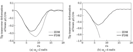
Fig.4 Responses of tip displacement of Beam with known large overall motions
3.2 Impacts of mass on dynamic responses of the system
Assume the parameters of the system as: ① For hub, radiusb=0.06 m, rotary inertiaJstar=1.16 kg·m2; ② For beam, lengthl=1.8 m, sectional areaA=2.5×10⁻⁴m2, rotary inertia of cross sectionI=1.302 1×10⁻¹⁰m4, bulk densityρ=2.766×10³kg/m3, Young’s modulus of elasticityE=6.9×10¹⁰N/m2; ③ For mass, positiond=0.9l and massmt=0.085 kg. The driving torque acting on hub is
(27)
whereTm=2 s, andThm=2 N·m.
① Impact of positiond(mtequals default value)
Fig.5 corresponds to the response curves of system when Mass lies at the positionsd=0.21 andd=0.8l. It can be seen from Fig.5 that, during the acting time of torque, the tip maximum response amplitude of Beam whend=0.8l is obviously larger than that whend=0.2l. After the cancellation of torque, obviously the tip steady state response amplitude of Beam when Mass lies at the positiond=0.8l is also larger than that whend=0.2l.
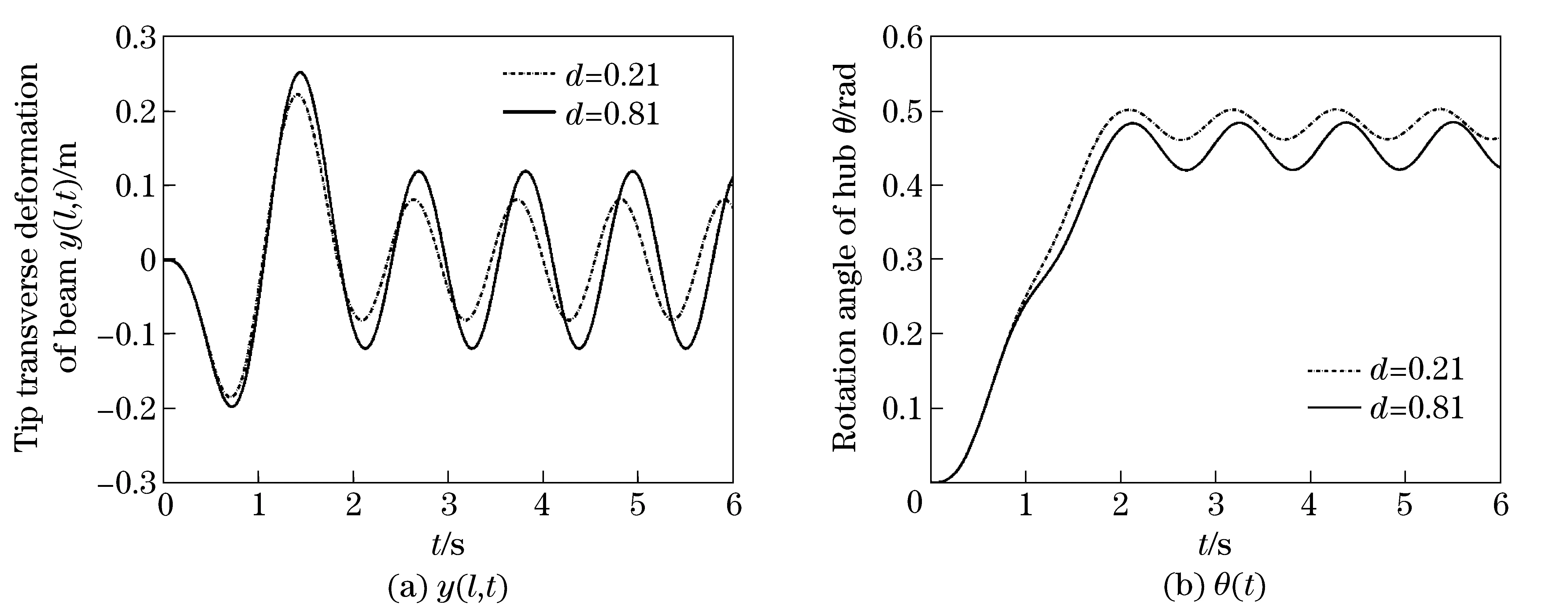
Fig.5 Responses of system when mass lies at different positions
From the analyses above, it can be inferred that: Mass has a softening effect on the dynamic behavior of the flexible beam, and the effect is more obvious when mass lies closer to the tip of beam. In order to investigate the impact of the mass position on the system, the position ratio ofRd=d/lis introduced. According to the restrictive condition, there isRd∈[0,1). Fig.6 shows the impact of the Mass position on the tip response of Beam. From Fig.6, whenRd≤0.3, the impact is negligible. WhenRd>0.3, the impact is quite obvious, and with the growth ofRd, the increasing processes of the maximum response amplitude and the steady state response amplitude are both approximate exponential growths. The conclusion here strongly support the inference at the beginning.
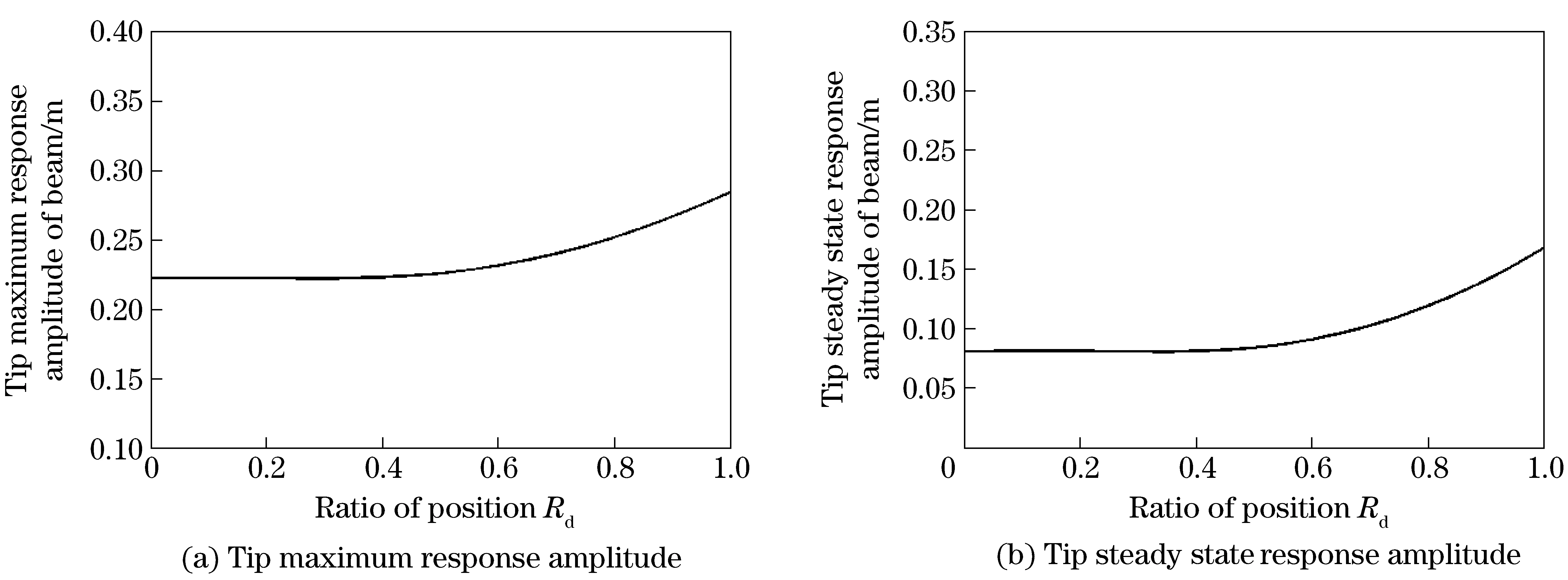
Fig.6 Impact of position ratio on the tip response amplitude of beam
② Impact of massmt(dequals default value)
Fig.7 corresponds to the response curves of the system whenmt=0 kg andmt=0.085 kg. During the acting time of torque, the tip maximum response amplitude of Beam with the mass is 0.263 m, and that without the mass is 0.223 m. After the cancellation of torque, the corresponding tip steady state response amplitudes are 0.141 m and 0.081 m respectively. Obviously, the response amplitude of Beam with the mass is larger.
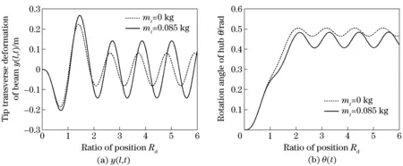
Fig.7 Responses of system when Mass has different masses
Referring to the inferences aboutd, it can be inferred aboutmtthat: Mass has a softening effect on the dynamic behavior of the flexible beam, and the effect is more obvious when its mass is larger. Introduce the mass ratioRM=mt/(ρAl). Restrict the mass ratio in the interval [0, 1]. Fig.8 shows the impact that the mass ratio makes on the tip response of Beam. It can be seen from Fig.8 that, the tip maximum response amplitude of Beam and the steady state response amplitude of beam increase with the growth ofRM, and the regular patterns are both approximately logarithmic growths.
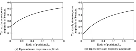
Fig.8 Impact of the mass ratio on the tip response amplitude of beam
4 Conclusions
A rigid flexible coupling system with a non-tip mass (hub-beam-mass) is investigated in this paper. By introducing the theory about mechanics problems in a non-inertial system, the dynamic equations are established. According to the theoretical analyses and numerical simulations, the following conclusions are obtained:
① A rational mechanism for the dynamic stiffening phenomenon when the rigid flexible coupling system is undergoing large overall motion is clearly offered in this paper. It is produced by the coupling effect of the centrifugal inertial load distributed on the flexible beam and the transverse vibration deformation of the beam.
② By using the Dirac function and the Heaviside function, the mass is incorporated into the dynamic equations of the system. According to the boundary conditions about the constrained modes, the position of mass is restricted in a rational interval. It should be pointed out that, this paper provides a complete set of program of solution for the modeling of a rigid flexible coupling system with a non-tip mass, containing how to establish the continuous dynamic equations, how to analyze the constrained modes, and how to deduce the finite dimensional state space equations which are suitable for controller design.
③ A comprehensive review of the impacts of mass properties (position and mass) on the dynamic response of the rigid flexible coupling system is carried out in this paper. The relevant inferences presented in this paper are verified: Mass has a softening effect on the dynamic behavior of the flexible beam, and the effect is more obvious when it has a larger mass, or it lies closer to the tip of beam.
[1] Tamer M Wasfy, Ahmed K Noor. Computational strategies for flexible multibody systems[J]. Applied Mechanics Reviews, 2003, 56(6): 553-613.
[2] Enrico Silani, Marco Lovera. Magnetic spacecraft attitude control: a survey and some new results[J]. Control Engineering Practice, 2005, 13(3): 357-371.
[3] Hu Qinglei, Shi Peng, Gao Huijun. Adaptive variable structure and commanding shaped vibration control of flexible spacecraft[J]. Journal of Guidance, Control, and Dynamics, 2007, 30(3): 804-815.
[4] Choura S, Jayasuriya S, Medick M A. On the modeling, and open-loop control of a rotating thin flexible beam[J]. Journal of Dynamic Systems, Measurement and Control, 1991, 113(1): 26-33.
[5] Kane T R, Ryan R R, Banerjee A K. Dynamics of a cantilever beam attached to a moving base[J]. Journal of Guidance, Control and Dynamics, 1987, 10(2): 139-151.
[6] Mayo J, Domínguez J. Geometrically non-linear formulation of flexible multibody systems in terms of beam elements: Geometric stiffness[J]. Computers and Structures, 1996, 59(6): 1039-1050.
[7] Yang Hui, Hong Jiazhen, Yu Zhengyue. Dynamics modeling of a flexible hub-beam system with a tip mass[J]. Journal of Sound and Vibration, 2003, 266(4): 759-774.
[8] Cai Guoping, Lim C W. Dynamics studies of a flexible hub-beam system with significant damping effect[J]. Journal of Sound and Vibration, 2008, 318(1-2): 1-17.
[9] Yu Jibang, Zhang Dingguo. Subsystem method for dynamic modeling of rigid-flexible coupling multibody system with dynamic stiffening[J]. Journal of Nanjing University of Science and Technology: Natural Science Edition, 2006, 30(4): 409-413. (in Chinese)
[10] García-Vallejo D, Sugiyama H, Shabana A A. Finite element analysis of the geometric stiffening effect. Part 1: a correction in the floating frame of reference formulation[J]. Journal of Multi-body Dynamics, 2005, 219(2): 187-202.
[11] Sugiyama Hiroyuki, Gerstmayr Johannes, Shabana Ahmed A. Deformation modes in the finite element absolute nodal coordinate formulation[J]. Journal of Sound and Vibration, 2006, 298(4-5): 1129-1149.
[12] Huang Yong’an, Deng Zichen, Yao Linxiao. An improved symplectic precise integration method for analysis of the rotating rigid-flexible coupled system[J]. Journal of Sound and Vibration, 2007, 299(1-2): 229-246.
[13] Graham G Sanborn, Ahmed A Shabana. On the integration of computer aided design and analysis using the finite element absolute nodal coordinate formulation[J]. Multibody System Dynamics, 2012, 22(2): 181-197.
[14] Graham G Sanborn, Ahmed A Shabana. A rational finite element method based on the absolute nodal coordinate formulation[J]. Nonlinear Dynamics, 2009, 58(3): 565-572.
[15] Dong Fuxiang, Hong Jiazhen, Zhu Kun. Initial conditions of impact dynamics[J]. Journal of Shanghai Jiaotong University, 2010, 15(3): 368-371. (in Chinese)
[16] Shen Shaopin, Li Zhibin. Attitude dynamics of a spacecraft with tip mass attached deploying flexible appendage[J]. Journal of Vibration and Shock, 2008, 27(5): 115-118, 178-179. (in Chinese)
[17] Bai Shengjian, Huang Xinshen. Dynamic modeling of large flexible spacecraft undergoing fast maneuvering[J]. Acta Aeronautica et Astronautica Sinica, 2009, 30(10): 1985-1992. (in Chinese)
[18] Han Qingpeng, Gao Peixin. Dynamic analysis of rigid-flexible manipulators undergoing a large overall motion condition[J]. Journal of machine design, 2013, 30(2): 27-31. (in Chinese)
[19] Li Cuichun, Meng Xiuyun, Liu Zaozhen. Dynamic modeling and simulation for the flexible spacecraft with dynamic stiffening[J]. Journal of Beijing Institute of Technology, 2015, 24(3):305-312.
[20] Liu Jinyang, Hong Jiazhen. Rigid flexible coupling dynamic analysis of flexible body[J]. Chinese Journal of Solid Mechanics, 2002, 23(2): 159-166. (in Chinese)
(Edited by Wang Yuxia)
10.15918/j.jbit1004-0579.201524.0402
V 414.33 Document code: A Article ID: 1004- 0579(2015)04- 0432- 09
Received 2013- 11- 26
E-mail: mengxy@bit.edu.cn
 Journal of Beijing Institute of Technology2015年4期
- Journal of Beijing Institute of Technology的其它文章
- Influence of shear sensitivities of steel projectiles on their ballistic performances
- Generalized ionospheric dispersion simulation method for wideband satellite-ground-link radio systems
- Multi-subpulse process of large time-bandwidth product chirp signal
- Factor-graph-based iterative channel estimation and signal detection algorithm over time-varying frequency-selective fading channels
- Nano-silica particles enhanced adsorption and recognition of lysozyme on imprinted polymers gels
- Similarity matrix-based K-means algorithm for text clustering