
Stability of a tumblehome hull under the dead ship condition*
2015-02-16 06:50:50GUMin顧民LUJiang魯江WANGTianhua王田華
水動力學(xué)研究與進(jìn)展 B輯 2015年3期
GU Min (顧民), LU Jiang (魯江), WANG Tian-hua (王田華)
Jiangsu Key Laboratory of Green Ship Technology, China Ship Scientific Research Center, Wuxi 214082 , China, E-mail: gumin702@163.com
Stability of a tumblehome hull under the dead ship condition*
GU Min (顧民), LU Jiang (魯江), WANG Tian-hua (王田華)
Jiangsu Key Laboratory of Green Ship Technology, China Ship Scientific Research Center, Wuxi 214082 , China, E-mail: gumin702@163.com
(Received May 11, 2014, Revised August 13, 2014)
Some methods for direct stability assessment under the dead ship condition were currently developed by the international maritime organization (IMO) under the Second Generation Intact Stability Criteria. Model tests and simulations are carried out to validate the numerical methods used in assessing the stability under the dead ship condition. This is done in three stages. Firstly, the uncoupled roll mathematical model (1 DOF) is adopted to calculate the roll motion based on the irregular beam waves and the steady wind. Secondly, a drift free experiment is conducted to measure the roll motion under irregular beam waves with zero speed, and then two restrained experiments with counter weights and four springs are performed under the same condition. Finally, the effects of the drift and sway motions on stability under the dead ship condition are then verified by experimental results, and the results of the numerical methods are compared to the results of the model experiments. It is concluded that more accurate numerical methods could be developed for assessing the direct stability under the dead ship condition.
dead ship condition, direct stability assessment, second generation intact stability criteria, irregular waves
Introduction
Some methods for direct stability assessment under the dead ship condition were currently developed by the international maritime organization (IMO) under the Second Generation Intact Stability Criteria. Some approaches based on probability assessment were investigated, such as the piece-wise linear method and the critical wave group method[1,2]. For the direct stability assessment under the dead ship condition, Japan and Italy carried out a Monte Carlo simulation on an uncoupled roll model with irregular beam winds and waves (1 DOF) in time domain for the direct stability assessment of the dead ship condition[3,4]. However, Italy’s 1 DOF approach contains too much simplications for a direct stability assessment, and thus this approach was not accepted by the majority of the working group.
Umeda et al.[5]performed physical model tests of capsizing in irregular beam waves with non-fluctuating wind and validated the results of the numerical method based on an uncoupled roll equation and piece-wise linear approach. Kubo et al.[6]developed a coupled sway-heave-roll-pitch (4 DOF) numerical model for assessing the stability under the dead ship condition, and it was concluded that the 4 DOF numerical model is better than the 1 DOF numerical model as compared with the model tests of capsizing in irregular beam waves with fluctuating wind. Ogawa et al.[7]pointed out that the drift speed affects the capsizing probability under the dead ship condition; and the capsizing probability of a passenger ship with drift is higher than that without, based on model experiments of a passenger ship under moored and drift conditions.
In order to develop a more reliable numerical method to analyze the stability under the dead ship condition, model experiments are conducted by using three methods: a drift free test, a restrained test with counter weights, and a restrained test with four springs. The effects of drift and sway motions on the stability under the dead ship condition are verified by experimental results, and the results of the uncoupled roll mathematical model (1 DOF) are then compared with the results obtained by model experiments. It is shown that a more precise numerical method should be developed for assessing the direct stability under the dead ship condition.
The authors pointed out[8]that the stability of a tumblehome hull with a low freeboard is vulnerable under the dead ship condition. The ONR tumblehome ship is selected in this study as the objective ship, which is provided by an IMO’s intercessional corresponding group as one of standard models for drafting second generation intact stability criteria.
1. Mathematical model
In order to calculate the probability of the unstability under the dead ship condition, the nonlinear and uncoupled equation with a stochastic wave excitation and a wind moment is used.
whereφis the roll angle,μthe linear roll damping coefficient,βthe quadratic roll damping coefficient, W the ship weight,Ixxthe roll moment of inertia Jxxthe added roll moment of inertia,GZ the righting arm, Mwind(t)the wind induced moment consisting of the steady and the fluctuating wind moments,Mwave(t)is the Froude-Krylov component of the wave exciting moment. The roll diffraction moment and the roll radiation moment due to the sway cancels out when the wave length is sufficiently longer than the ship breadth. The dots denote differentiation with respect to time.
The wind induced excitation moment can be calculated by the following equation

where ρa(bǔ)iris the air density,Cmthe aerodynamic drag coefficient,Uwthe mean wind velocity,U( t) the fluctuating wind velocity calculated by the Davenport spectrum[9],ALthe lateral windage area, and HCthe height of the center of the wind force from the center of the hydrodynamic reaction force.
The fluctuating wind velocity is calculated by the following equation, where the Davenport spectrum[10]is used.
where
The Froude-Krylov component of the wave exciting moment can be calculated by the following equation

where γ is the effective wave slope coefficient, which can be calculated by the recommended formula in the 2008IS code or the strip method[11], and Θ (t) is the wave slope calculated from the ITTC wave spectrum[ 12] as follows:

H1/3is the significant wave height and T01is the mean wave period.
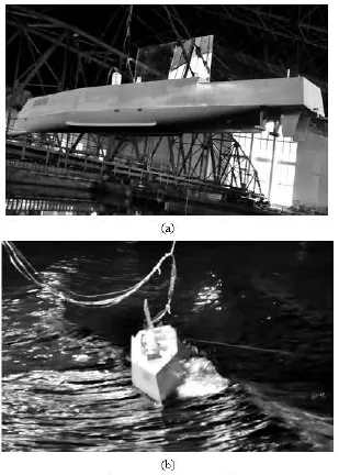
Fig.1 The ONR Tumblehome model
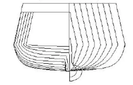
Fig.2 ONR Tumblehome lines
2. Model and test description
The tested model is the ONR Tumblehome provided by the coordinator of the corresponding group of the second generation intact stability criteria, and its superstructure is replaced by a quadrate organic glass structure (Figs.1, 2). The scale ratio is λ=40.526and the model length between the perpendiculars(LPP)is 3.8 m. The other geometrical and mechanical data of the model are listed in Table 1.
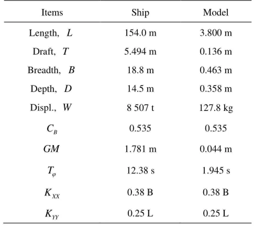
Table1 Principal particulars of the ONR tumblehome
The experiment is performed in the seakeeping basin (of 69 m in length, 46 m in breadth and 4 m in depth) in the China Ship Scientific Research Center, equipped with a flap wave maker at two adjacent sides of the basin. A servo-needle wave height sensor is used to measure the incoming waves. It is placed at the port side, 1 m from the model and the left-fore perpendicular.
Three mooring methods are adopted in the test. Firstly, the model is drifted freely in the beam seas with two protected ropes to avoid the ship from escaping at the worst scenario due to the yaw moment[13]as shown in Fig.3(a). Secondly, the ship model is made perpendicular to the wave direction in the test through a wire system of four wires connected to the ship model at the bow and the stern, respectively, and close to the water surface as shown in Fig.3(b). In the second method, the drift and the yaw may be softly restrained by the counter weight, however, the heave, the pitch, the roll and the sway are free. Thirdly, the ship model is kept perpendicular to the wave direction by a wire system, with four wires connected to the ship model through four short springs at the bow and the stern, respectively, in level with the water surface as shown in Fig.3(c). In the third method, the other ends of the four wires are fixed steadily, so the drift is restrained and the heave, the pitch and the yaw are softly restrained.
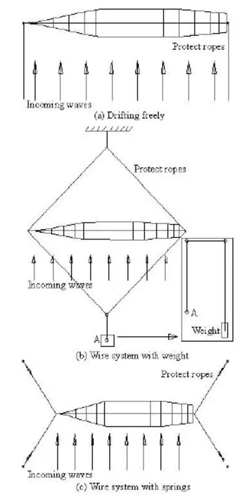
Fig.3 Layout of experimental set-ups
Roll decay tests are carried out under calm water conditions. The model is heeled to an initial heeling angle and then released. This series of tests are used to determine the roll damping and eventually its linear and nonlinear components[14], which are then used in simulations, as shown in Fig.4.
Irregular wave’s spectrums generated with five seed numbers by the wave maker agree well with the ITTC Spectrum, as shown in Fig.5. The roll, pitch and yaw amplitudes are measured by the micro electromechanical system (MEMS) based gyroscope placedon the ship model.
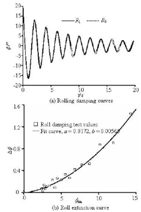
Fig.4 Roll damping curves and the extinction curve (a,b are linear and square extinction coefficients)
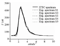
Fig.5 Wave spectrum

Fig.6 Roll amplitudes with T =12.38s,Fr =0,χ=90o, GM=1.781m
3. Results and discussions
The roll amplitudes from the simulations using the 1 DOF approach in a regular beam wave are larger than those from model experiments, with the exception of the case of small wave height as shown in Fig.6. The discrepancy is attributed to the assumption of a linear relationship between the wave exciting moments and the wave amplitude in the 1 DOF simulation. The roll amplitudes from the free drift test and the restrained tests with counter weight are in agreement with each other, and with the results from restrained tests with four springs at low wave heights, however, they are larger at high wave heights. In the second method, only the drift and the yaw are weakly restrained by the counter weight, while in the third method the drift is restrained, and the heave, the pitch and the yaw are weakly restrained. The effects of test methods on the roll amplitudes are reduced at low wave heights.
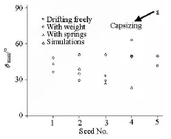
Fig.7 Maximum roll angles with H1/3=14.0 m,T01=12.38s, Fr =0,χ=90o,GM=1.781m
Capsizing occurs at seed number 5 in restrained tests with counter weight and four springs when encountering a large wave as shown in Figs.7 and 8. However, no capsizing is witnessed in free drift tests and the maximum roll angle is 41.5o. It is because the free drift and sway could damp the instantaneous large wave force on the ship hull and reduce the water on the deck.
The maximum roll angle is63oin the restrained tests with counter weight and is50oin the free drift test at seed number 4 when encountering two large waves, as shown in Fig.7. The difference between the maximum roll angles is due to the same reason as stated above. The maximum roll angle is only23.4oin the restrained test with four springs at seed number 4 as the ship motion is restrained by the four wires and springs. The differences between the maximum roll angles are not very large at seed numbers 1, 2, 3 among three model tests, without encountering a severe wave, as shown in Fig.7.
The numerical simulations at different seed numbers predict larger roll angles as shown in Fig.7. The capsizing does not occur in the simulations as the largest encounter wave in the experiments are not reproduced in the numerical simulations.
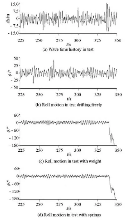
Fig.8 Wave record and roll time history with H1/3=14.0 m, T=12.38s,Fr =0,χ=90o,GM=1.781mand01seed number 5

Fig.9 Probability of upcross with H1/3=14.0 m,T01=12.38s, Fr =0,χ=90o,GM=1.781m
The probabilities of up-cross[15]in experiments and simulations are calculated as shown in Fig.9.Pupis the up-cross number per second, and the experimental duration is 10 min in 1 h simulations. Although capsizing is not observed at seed number 5 in the free drift test, the probability of up-cross at seed number 1, 3, 5 without wave loads on the superstructure is larger than those in other two tests with wave forces on the superstructure, thus the capsizing probability with drift motions is higher than those without drift motions, as observed by Ogawa et al.[7]. However, in this study, capsizing occurs in both restrained tests and does not occur in free drift tests.
In conclusion, the 1 DOF simulation results are found to overestimate the maximum roll angle and the probability of up-cross as shown in Figs.7 and 9, with the exception of the cases of seed numbers 4 and 5. As discussed above, a more advanced numerical modelling is desirable to take account of both drift and sway motions.
4. Conclusions
From the results of the experimental and numerical studies of the stability under the dead ship condition, the following conclusions are drawn:
(1) The capsizing probabilities with drift motions are higher than those without drift motions, yet capsizing only occurs in the restrained tests in the experiments in this study.
(2) It is recommended that more accurate numerical models should be developed for assessing the direct stability under the dead ship condition to include the effects of the drift and the sway on the roll motion in beam seas.
(3) Restrained tests with counter weight tend to produce more conservative results than the free drift test for the capsizing prediction.
Acknowledgement
This paper was presented at the 13th International Ship Stability Workshop. Prof. Umeda N. from Osaka University (Japan) gave useful advices on predicting stability under dead ship condition and the standard model ship.
[1] THEMELIS N., SPYROU K. J. Probabilistic assessment of ship stability[J]. Transactions of the Society of Naval Architects and Marine Engineers, 2007, 115: 181-206.
[2] ISKANDAR B. H., ANDUMEDA N. Some examinations of capsizing probability calculation for an Indonesian RoRo passenger ship in waves[J]. Journal of Kansai Society of Naval Architects, 2001, 236: 81-86.
[3] BULIAN G., FRANCESCUTTO A. Safety and operability of fishing vessels in beam and longitudinal waves[J]. Transactions of the Royal Institution of Naval Architects Part B: International Journal of Small Craft Technology, 2006, 148(2): 1-16.
[4] MCTAGGART, K., ANDDEKAT J. O. Capsizing risk of intact frigates in irregular seas[J]. Transactions of the Society of Naval Architects and Marine Engineers, 2000, 108(492): 147-177.
[5] UMEDA N., IZAWA S. and SANO H. et al. Validation attempts on draft new generation intact stability criteria[C]. Proceedings of the12th International Ship Stability Workshop. Washington DC, USA, 2011, 19-26.
[6] KUBO T., UMEDA N. and IZAWA S. et al. Total stability failure probability of a ship in irregular beam wind and waves: Model experiment and numerical simulaton[C]. Proceedings of 11th International Conference on the Stability of Ships and Ocean Vehicles. Athens, Greece, 2012, 39-46.
[7] OGAWA Y., De KAT J. O. and ISHIDA S. Analytical study of the effect of drift motion on the capsizing probability under dead ship condition[C]. Proceedings of 9th International Conference on the Stability of Ships and Ocean Vehicles. Rio de Janeiro, Brazil, 2006, 1: 29-36.
[8] GU M., LU J. and WANG T. An investigation on stability under dead ship condition of a tumblehome hull[C]. Proceedings of 11th International Conference on the Stability of Ships and Ocean Vehicles. Athens, Greece, 2012, 593-598.
[9] BULIAN G., FRANCESCUTTO A. A simplified modular approach for the prediction of the roll motion due to the combined action of wind and waves[J]. Journal of Engineering for the Maritime Environment, 2004, 218(3): 189-212.
[10] PAROKA D., OHKURA Y. and UMEDA N. Analytical prediction of capsizing probability of a ship in beam wind and waves[J]. Journal of Ship Research, 2006, 50(2): 187-195.
[11] BULIAN G., FRANCESCUTTO A. Experimental results and numerical simulations on strongly nonlinear rolling of multihulls in moderate beamseas[J]. Proceedings of the Institution of Mechanical Engineers-Part M-Journal of Engineering for the Maritime Environment, 2009, 223(2): 189-210.
[12] PAROKA D., UMEDA N. Capsizing probability prediction for a large passenger ship in irregular beam wind and waves: Comparison of analytical and numerical methods[J]. Journal of Ship Research, 2006, 50(4): 371-377.
[13] UMEDA N., KOGA S. and UEDA J. et al. Methodology for calculating capsizing probability for a ship under dead ship condition[C]. Proceedings of the 9th International Ship Stability Workshop. Hamburg, Germany, 2007.
[14] IKEDA Y. Prediction methods of roll damping of ships and their application to determine optimum stabilization devices[J]. Marine Technology, 2004, 41(2): 89-93.
[15] BELENKY V., WEEMS K. M. and LIN W. M. Numerical procedure for evaluation of capsizing probability with split time method[C]. 27th Symposium on Naval Hydrodynamics. Seoul, Korea, 2008.
* Project supported by Ministry of Industry and Information Technology of China (Grant No. [2012] 533)
Biography: GU Min (1962- ), Male, Master, Professor
LU Jiang,
E-mail: lujiang1980@aliyun.com

- 水動力學(xué)研究與進(jìn)展 B輯的其它文章
- United friction resistance in open channel flows*
- Ski jump trajectory with consideration of air resistance*
- Selection of organic Rankine cycle working fluids in the low-temperature waste heat utilization*
- Multi-scale Runge-Kutta_Galerkin method for solving one-dimensional KdV and Burgers equations*
- Numerical study of the performance of multistage Scaba 6SRGT impellers for the agitation of yield stress fluids in cylindrical tanks*
- The impact of macroalgae on mean and turbulent flow fields*