
Research and simulation of two-level grid-connected photovoltaic inverter system
2014-09-07 06:37:54ANBinGONGMaofaSUYanpingWANGZhiwenLILanbing
AN Bin,GONG Mao-fa,SU Yan-ping,WANG Zhi-wen,LI Lan-bing
(College of Electrical Engineering and Automation,Shandong University of Science and Technology,Qingdao 266590,China)
Solar energy is a kind of clean and renewable energy nowadays,so it has aroused more and more concern. The PV power generation system can be divided into two kinds of the PV off-grid power system and PV grid power system[1]. The PV off-grid power system is used for rural electrification,communications and industrial applications. The PV grid power system is mainly used for combining buildings in a city,as well as used for large desert PV power plants. Such applications have become the mainstream of the PV market[2].
The front stage Boost converter with the method of improved CVT start which is in combination with the variable step size disturbance observer method can realize the simulation of MPPT. The advantages of the method are that it can quickly track the maximum power point and reduce the disturbance near the maximum power point. Further,the method can also save energy.
The back stage network side inverter generally adopts the method of double loop to control the voltage and current. It is a relatively mature classical control method and easy to implement. However,it has slow dynamic response speed and needs long adjustment time. The output current waveform quality is weak when rapid changes occur in the light condition. In this paper,the method of the deadbeat control is adopted. Deadbeat control method has the advantages of fixed switching frequency,good dynamic response and low harmonic content. In addition,it can output high-quality grid current.
1 Control principle of two-level grid-connected photovoltaic system
Fig.1 shows the two-level PV power system circuit. The controller 1 is able to realize the maximum power point tracking which means that it achieves MPPT control of the front stage Boost converter[3]. Controller 2 achieves control of the unity power factor and control of DC side voltage,which realizes that frequency and phase of the grid current are the same as the grid voltage[4].
1.1 MPPT control based on front stage DC/DC converter
The output voltage of the Boost converter is controlled by the network side inverter,so adjusting the Boost converter switching duty cycle is equal to adjusting the input current of the Boost converter. In this way,output voltage of the photovoltaic cells is regulated. According to the output voltage and output current of the photovoltaic cells which are detected,the Boost converter can regulate operating point of the photovoltaic cell voltage commandUrefby MPPT control algorithm. Then the sampled value of the output voltage of the photovoltaic cellsUPVis subtracted fromUref,and the input voltage closed-loop control of the Boost converter is realized by a PI regulator. So the MPPT control of photovoltaic cells is implemented.
In this paper,the maximum power point tracking is achieved by using method of the improved CVT start which is in combination with the variable step size disturbance observer. Larger step of voltage disturbance can be able to improve the tracking speed and reduce the time of photovoltaic cells in the area away from MPP. The tracking accuracy is certified by using smaller step of voltage disturbance in area near the MPP region.
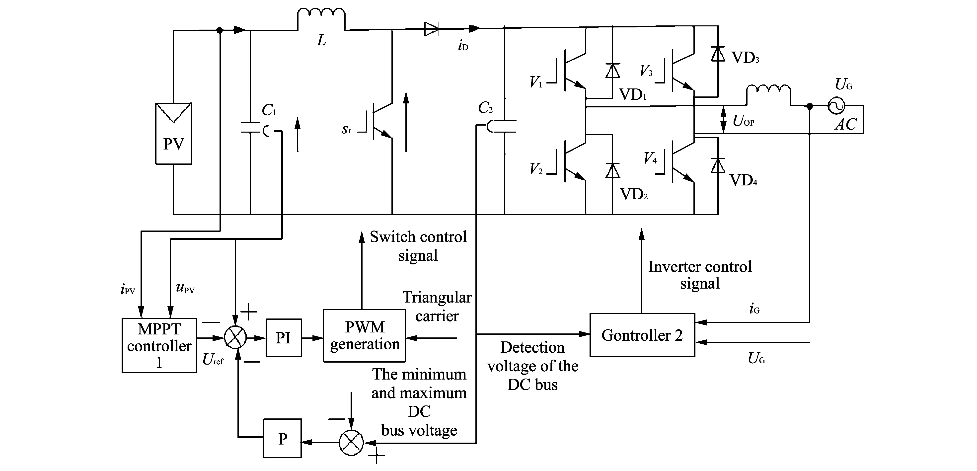
Fig.1 Two-level PV power system circuit
1.2 PV grid-connected inverter control
Deadbeat control principle is described as follows. Firstly,the next switching cycle of PWM pulse width is calculated by the state equation of the inverter and output feedback signal[4]. Secondly,the tube’s turn-on and turn-off of the power inverter bridge is controlled according to the pulse width[5]. Ultimately,output waveform of the inverter is displayed. The deadbeat control can adapt to the PV grid-connected inverter control because it has advantages of good dynamic performance,undistorted output waveform,short transient response time and so on[6-9].
The deadbeat control scheme is adopted by the back stage network side inverter. Eq.(1) can be obtained from Fig.1. That is
Uop=UG+jwLiG,
(1)
whereUopis output voltage of the grid inverter;UGis grid voltage;iGis grid current;Lis inductance of the boost circuit.
The time domain circuit equation Eq.(2) is obtained by Eq.(1).
(2)
whereiLis output reference current of the inverter.
Eq.(3) is discrete process of Eq.(2). We have
whereTsis sampling period;iL[n]is the current value which is sampled at then-th times about inductanceL;Uop[n]is the arithmetic mean ofUopat then-th sampling period;Ugrid[n]is the arithmetic mean ofUgridduring then-th sampling period;iL[n]is the arithmetic mean ofiLduring the nth sampling period.
In fact,Uop[n]is the pulse voltage,and its pulse widthD[n]is as follows
(4)
Output voltage of the inverter can be obtained by controlling the sampled pulse width,so controllingUop[n]means to control the output voltage of the inverter.
Eq.(5) is calculated by Eq.(3).
UG[n]+RiL[n],
(5)
ip[n+1]can be used instead ofiL[n+1]in Eq.(5) if the inductor current is able to track the reference current at the sampling time of (n+1). As a result,Eq.(6) is obtained
UG[n]+RiL[n].
(6)
Eq.(7) is calculated when Eq.(4) is put into Eq.(6).
In analysis of the deadbeat control principle presented here,the inverter reference current signal at the next cycle is the premise of obtaining the inverter pulse width at the next sampling cycle,and the next PWM cycle time is calculated by the above formula. Fig.2 shows the schematic of reference current obtained by the grid side inverter.
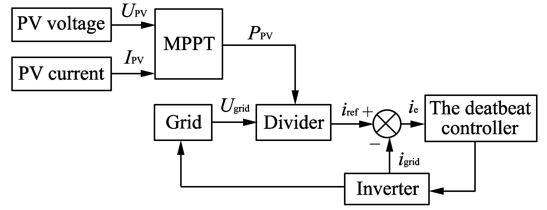
Fig.2 Schematic of reference current obtained by inverter
1.3 Algorithm two-level grid-connected photovoltaic system
Fig.3 shows algorithm flow chart of the two-level grid-connected photovoltaic system. Disturbance step is adjusted adaptively when the difference is not 0 but betweenVkandVk-1. The end of the return will be completed ifVkis equal toVk-1. Firstly,the open voltage of PV system is sampled,and the initial voltage of CVT is set. So the output voltage of PV cell is controlled,moving from the open voltage to the maximum power point voltage. Secondly,the variable step disturbance observer method is adopted when the output voltage reaches the needed point. Then,output powerPcan be obtained by the MPPT control strategy,and valid value of the reference current is calculated when powerPis divided by the grid voltage. Then,reference current signal of the inverter which is at the next cycle is determined according to the phase of the grid voltage. Finally,the inverter pulse width is able to control tube’s turn-on and turn-off of the power inverter bridge.
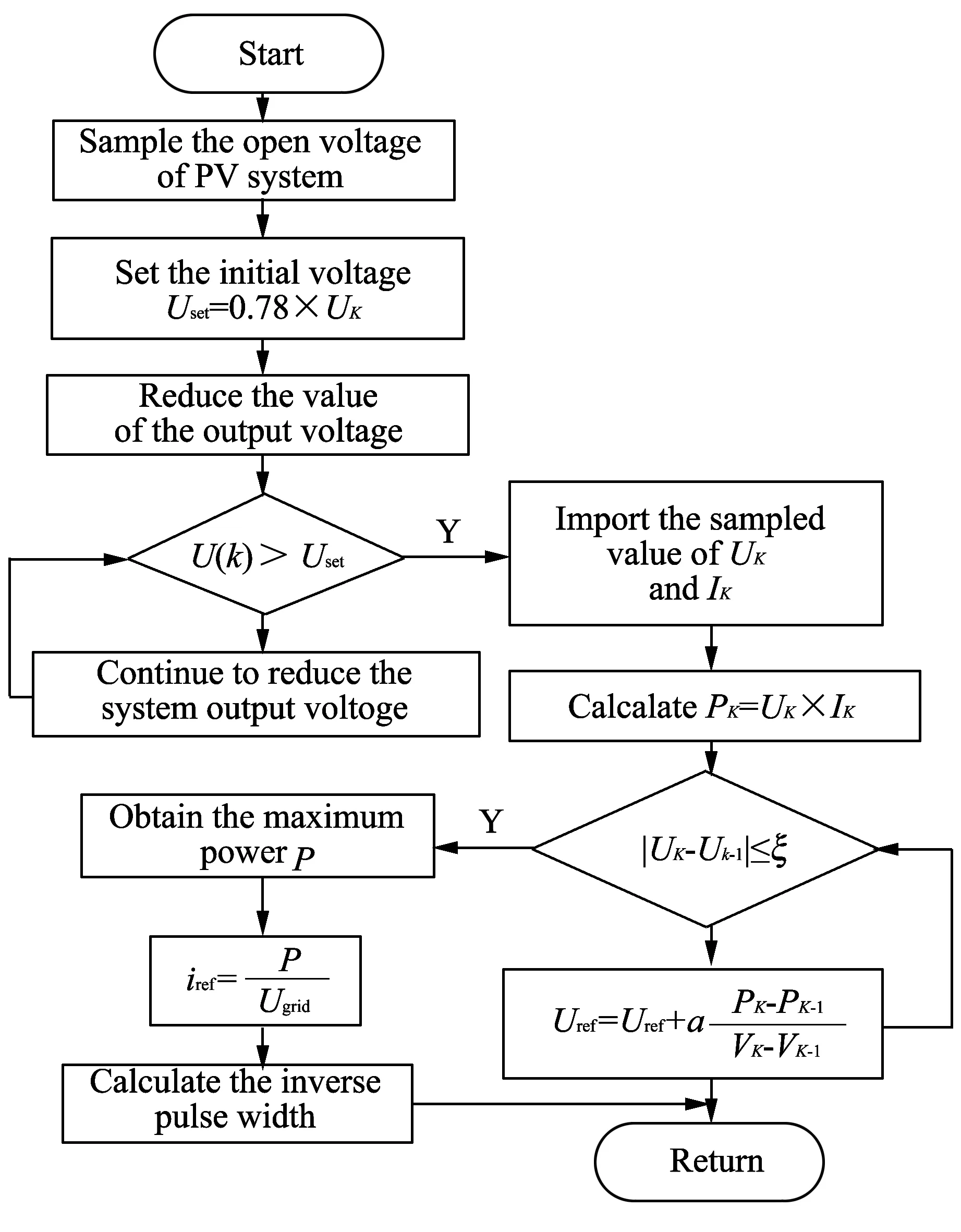
Fig.3 Algorithm flow chart of the two-level grid-connected photovoltaic system
2 Simulation and analysis
The simulation about the Boost circuit parameters are as follows. The switching frequencyfis 10 kHz; inductanceLis 6 mH; DC capacitorCis 1 500 μF. The two-level photovoltaic power generation system simulation model is set up based on the above parameters,as shown in Fig.4.
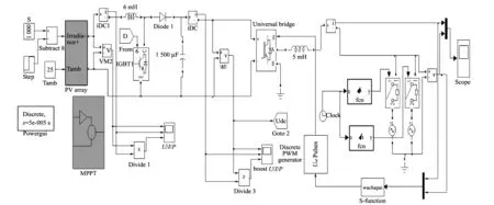
Fig.4 Two-level photovoltaic power generation system simulation model
Simulation diagram is shown in the MPPT control model based on the front stage DC/DC converter in Fig.5. The optimal state is realized whenais 0.01 in Eq.(8),compared with various step curves which concludes different colors. In other words,the tracking speed is the fastest and the volatility is the minimum,so MPPT tracking is better realized.
(8)
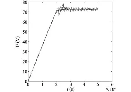
Fig.5 Voltage tracking diagram of MPPT control
Simulation results of the double loop which controls voltage and current are shown in Fig.6. The current can be able to track the voltage well,but the output current waveform is distorted and the waveform quality is not high.
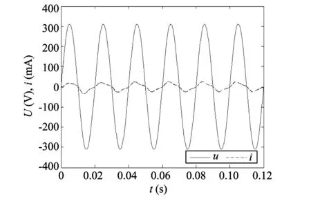
Fig.6 The simulation of double loop
Fig.7 shows the wavefosm that the current can track the grid voltage in the deadbeat control model of the network side inverter. The grid current can track voltage quickly to achieve!the same frequency and phase of the grid current and grid voltage. The grid current waveform will be able to maintain stability after 0.01 s when frequency of uhe grid voltage is from 50 Hz to 60 Hz at 0.08 s. So the grid current can track the grid voltage precisely. The waveform in Fig.7 proves that there is short transient time and good steady-state performance in the deadbeat control.
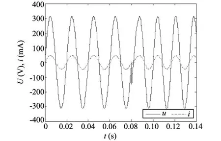
Fig.7 Waveform that current tracks the grid voltage
3 Conclusion
Simulation model of the two-level PV power system is put forward in this paper. The simulation module is realized in the simulation environment. The front stage Boost converter uses the method of improved CVT start which is in combination with the variable step size disturbance observer method realizes the simulation of MPPT. The back stage network side inverter uses the method of the deadbeat control to control the grid inverter current. Current and voltage of the grid have the same frequency and phase. The maximum power point tracking and grid inverter control are relatively independent in the simulation model. The entire system is not only conducive to the modular design but also more flexible and reliable.
[1] ZHANG Xing,CAO Ren-xian. Solar photovoltaic power generation and inverter control. Beijing: China Machine Press,2010.
[2] LIU Bang-yin,DUAN Shan-xu,LIU Fei. Photovoltaic array maximum power point tracking based on improved perturbation and observation method. Transactions of China Electrotechnical Society,2009,24(6): 91-94.
[3] JI Juan-zao,ZHOU Wei,XIAO Qiang. Maximum power point tracking of photovoltaic array based on improved perturb and observe algorithm. Power Electronics,2012,46(8): 29-31.
[4] CHENG Jun-zhao,WU Xi-ke,ZUO Wen-xia. Boost-based two-level grid-connected photovoltaic inverter system. High Voltage Engineering,2009,35(8): 2048-2051.
[5] ZHANG Chao,WANG Zhang-quan,JIANG Yan-jun,et al. Implementation of a deadbeat current controller for photovoltaic grid-connected inverters. Power Electronics,2007,41(7): 3-5.
[6] YAN Hong-lin,GONG Mao-fa,WANG Jing-jing. Research and simulation of single-phase photovoltaic grid-connected inverter deadbeat control. Electronics Quality,2012,(9): 12-14.
[7] WANG Fei,XIE Lei,ZHOU Yi-ren. Realization and research on control strategy of single phase photovoltaic grid-connected inverter. Power Electronics,2009,43(11): 24-25,40.
[8] LIU Sheng-rong. Design and development of PV inverter based on digital signal processor. Guangzhou: South China University of Technology,2010.
[9] ZHAN Xiong,LU Jia-ling,ZHOU Ying-ying. Study on deadbeat control method used to single-phase inverters. Power Supply Technologies and Applications,2003,6(10): 524-526.
[10] TANG Li-li,ZHENG Qiong-lin. Research on main circuit parameters selection of single-phase pwm rectifier. Journal of Northern Jiaotong University,2000,24(4): 98-102.
 Journal of Measurement Science and Instrumentation2014年2期
- Journal of Measurement Science and Instrumentation的其它文章
- Application of Kalman filter on mobile robot self-localization
- Design of a titl angle measurement system based on ADXL345 sensor
- Status and development trend of asphalt foaming process
- Research on temperature control module of injection molding machine based on C8051F020
- Design and application of integrated automation system platform of mine based on PON
- A method of elimination of undesired resonant points of microstrip antenna by cutting U-shaped slot on the ground