
Unified Model of Purification Units in Hydrogen Networks*
2014-07-18 12:09:48WUSidong吳思東WANGYufei王彧斐andFENGXiao馮霄SchoolofChemicalEngineeringTechnologyXianJiaotongUniversityXian70049ChinaStateKeyLaboratoryofHeavyOilProcessingChinaUniversityofPetroleumBeijing049China
WU Sidong (吳思東), WANG Yufei (王彧斐)and FENG Xiao (馮霄),**School of Chemical Engineering & Technology, Xi’an Jiaotong University, Xi’an 70049, ChinaState Key Laboratory of Heavy Oil Processing, China University of Petroleum, Beijing 049, China
Unified Model of Purification Units in Hydrogen Networks*
WU Sidong (吳思東)1, WANG Yufei (王彧斐)2and FENG Xiao (馮霄)2,**
1School of Chemical Engineering & Technology, Xi’an Jiaotong University, Xi’an 710049, China2State Key Laboratory of Heavy Oil Processing, China University of Petroleum, Beijing 102249, China
Purification processes are widely used in hydrogen networks of refineries to increase hydrogen reuse. In refineries, hydrogen purification techniques include hydrocarbon, hydrogen sulfide and CO removal units. In addition, light hydrocarbon recovery from the hydrogen source streams can also result in hydrogen purification. In order to simplify the superstructure and mathematical model of hydrogen network integration, the models of different purification processes are unified in this paper, including mass balance and the expressions for hydrogen recovery and impurity removal ratios, which are given for all the purification units in refineries. Based on the proposed unified model, a superstructure of hydrogen networks with purification processes is constructed.
purification process, hydrogen network integration, impurity removal ratio, refinery
1 INTRODUCTION
In recent years, increasingly strict environmental and product-quality regulations, and the change of crude oil to high-sulfur and heavier oil are forcing refineries to increase their hydrotreating and hydrocracking. The result is that the hydrogen demand is increasing sharply, which made hydrogen become an expensive utility [1].
To cope with this problem, the effective use of hydrogen is of significant importance. By now, hydrogen network integration (HNI) is recognized as the most effective method for refinery hydrogen management [2]. For hydrogen network integration, process hydrogen streams should be reused as fully as possible to reduce the hydrogen utility consumption. Purification, by upgrading hydrogen concentration of some streams, is an effective way to increase the hydrogen reuse at relative low cost [1, 3].
In a hydrogen network, in addition to hydrogen concentration, each hydrogen sink (for example, hydrotreating or hydrocracking units) requires also limits on certain impurities such as H2S and CO [2]. Therefore, in refineries, hydrogen purification techniques include hydrocarbon, hydrogen sulfide (H2S) and CO removal units.
Hydrocarbon removal units include pressure swing adsorption (PSA), membrane and cryogenic process [4]. There are several methods to remove H2S: dry desulfurization, wet desulfurization, bio-desulfurization and desulfurization by membrane. Wet desulfurization process is widely used. This process utilizes an aqueous absorbent in a column to absorb H2S and yields a substantial H2S-free gas [5]. In industrial applications, the CO removal process is usually coupled with a PSA process. Thus, a PSA process can be either with or without CO removal. Currently, light hydrocarbon recovery from hydrogen source streams is a trend to increase economic benefit of a refinery.
In the work on hydrogen network integration, at first the purification is treated as a fixed process and both the concentration and flowrate of purification streams are termed as fixed values [6-14]. Then, it is realized that a hydrogen network should be optimized with purification processes as a whole to achieve the minimum hydrogen utility consumption [1]. Hydrocarbon removal units were considered first [1, 4, 12]. After that, hydrogen sulfide removal processes were also considered [5]. Up to now, CO removal processes and light hydrocarbon recovery processes are not concerned.
Because different purification processes have different separation principles (adsorption, membrane, etc.), up to now, each purification process has its own model. Even in the superstructure of a hydrogen network, different purification processes have different blocks [2, 4, 5]. This makes the superstructure complicated and the solving process more difficult.
Although different purification processes have different separation principles, from the point of view of hydrogen network integration, the main description for each purification process only concerns mass balance and concentration constraints. Therefore, the models of purification processes can be unified, which is just the aim of this paper.
2 EXISTING MODELS
2.1 PSA process without CO removal
The PSA process separates the mixture stream by utilizing an adsorbent with different adsorb abilities for different components. The total mass balance is [2]

where F is flowrate, the superscript (PSA) means PSAprocess, and the subscript R, in and P denote residual, inlet and product, respectively.
The mass balance for component i is [2]

where y is concentration and subscript i means component i.
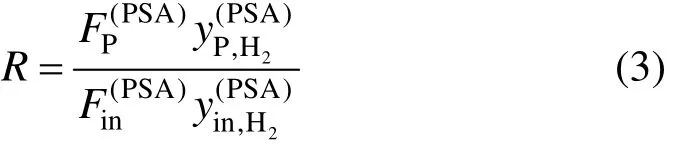
The hydrogen recovery ratio R is defined in Eq. (3), which varies according to the feed purity, adsorption pressure and tail gas pressure [3].
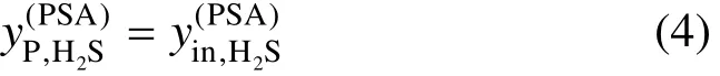
The concentration of hydrogen sulfide is assumed to be identical during the process, that is [2]
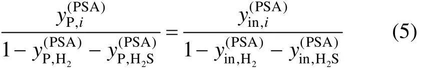
The hydrocarbon components are assumed to be removed at an equal proportion as follows [2].
It should be noted that CO is not considered in the model.
2.2 Membrane process
The membrane separation is operated by adopting a permselective membrane with permeability varying along with components. The total mass balance is [2]

where superscript memb means membrane process. The mass balance for component i is [2]
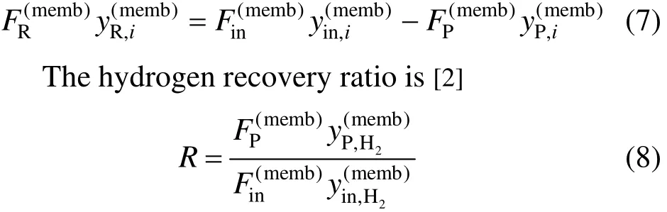
The hydrogen sulfide concentration of the product stream is assumed to be equivalent to the inlet stream [2].

It should be noted that not only CO but also the removal proportion of each hydrocarbon component are not considered in the model.
2.3 Desulfurization process
H2S removal units are usually modeled as mass exchangers. The hydrogen sulfide removed by a desulfurization column is a very tiny part of the mass stream, and therefore the inlet and outlet flowrates of a desulfurization column are assumed to be identical, as shown in Eq. (10) [5].
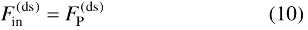
where superscript ds means desulfurization process.

3 THE UNIFIED MODEL OF PURIFICATION PROCESSES
A purification process usually generates two outputs from the feed (Fin, yin,i), one of which with higher hydrogen concentration is the purified product (FP, yP,i), and the other with lower hydrogen concentration is termed as residual or tail gas (FR, yR,i), as shown in Fig. 1.
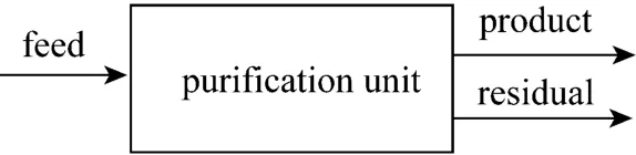
Figure 1 A purification unit
For a process with only one output like the desulfurization process, it can be taken as a specific case of the unified model with FR=0.
Then we have the total mass balance as shown in Eq. (12).

The mass balance for component i is

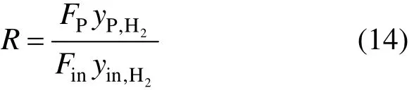
The hydrogen recovery ratio R is
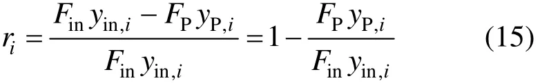
The removal ratio riof component i during the purification process is defined as
Equations (12) to (15) are the unified model of purification processes. Compared to all the existing models for different kinds of purification processes, it can be seen that the unified model is in full agreement.
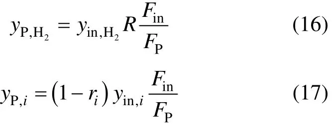
From the above equations, the outlet concentrations (the concentration of the product stream) of hydrogen and other components from a purification process can be calculated by Eqs. (16) and (17), respectively.
With the unified model of purification processes, all purification processes can be expressed in the same block in the superstructure of a hydrogen network. In this way, the superstructure will be simpler, and the mathematical model for the hydrogen network integration will be easier to establish.
4 HYDROGEN RECOVERY RATIO AND IMPURITY REMOVAL RATIO
The hydrogen recovery ratio and impurity removal ratio for each impurity should be determined before performing hydrogen network integration, which depends on the characteristics of the used purification units.
Normally, for the purification units mainly used to upgrade hydrogen concentration (for example, PSA and membrane), the hydrogen recovery ratio will be determined first, and the impurity removal ratios will be deduced accordingly. For the purification units mainly used to remove a kind of impurity, the removal ratio of the impurity will be determined first, and the hydrogen recovery ratio and the removal ratios of other impurities will be deduced accordingly.
From industrial experiences, the following equations can be obtained for each kind of purification processes.
4.1 PSA process without CO removal
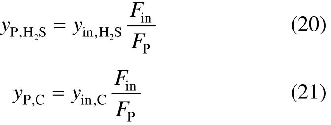
For a PSA process without CO removal, the hydrogen recovery ratio will be determined first. Not only H2S but also CO+CO2cannot be removed. Thus,
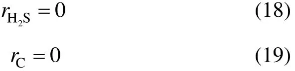
where the subscript C means CO+CO2.
Then, the concentrations of components H2S and CO+CO2in the product can be obtained as follows, respectively.
It should be noted that the assumption for the product concentrations of components H2S [Eq. (4)] from Ref. [5] is not correct compared with Eq. (20) becausein a PAS process is not very close to 1.
For other components, the removal ratio can be assumed as the same as follows.

4.2 PSA process with CO removal
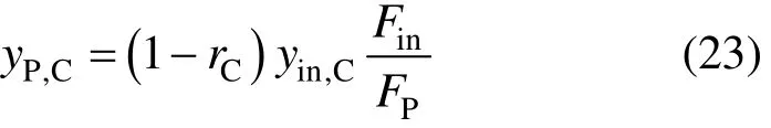
For a PSA process with CO removal, the hydrogen recovery ratio and the removal ratio of CO+CO2will be determined first. It should be noted that rCis not zero and the product concentration of component CO+CO2is
H2S still cannot be removed, whose removal ratio is also expressed with Eq. (18). For other components, the removal ratio can be also assumed as the same and can be calculated by Eq. (22).
4.3 Membrane process
In the membrane separation process, different components have different permeability, and thus the removal ratios for different components are also different. But normally, these components can be divided into two groups. The first group includes H2, H2S and CO2, which are termed as “fast gas” in industries. The another group has hydrocarbon components and CO, which are termed as “slow gas” in industries.
As an approximation, it can be assumed that the removal ratios for the components termed as “fast gas” are the same and equal to the portion of unrecovered hydrogen as follows.

The removal ratios for the components termed as“slow gas” are also the same and can be calculated by Eq (25).
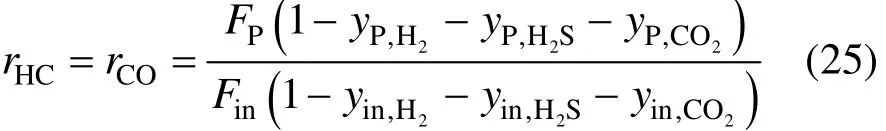

The hydrogen recovery ratio and the removal ratio of other impurities are listed below, respectively.
where subscript HC means hydrocarbon.
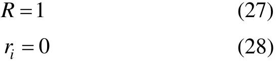
4.4 Desulfurization process
For a desulfurization process, it can be considered that only H2S is removed. Although tiny CO2can be removed at the same time, it can be ignored. So the removal ratio for H2S,2HSr, is determined first. Then the product concentration of component H2S is
Therefore, except H2S, the concentration of component i in the product stream, including H2, is almost identical during the process as follows.
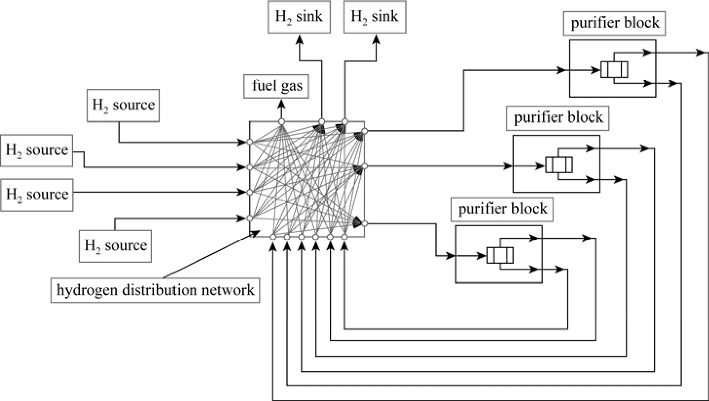
Figure 2 A superstructure for the hydrogen network with purification processes

4.5 Light hydrocarbon recovery process
The light hydrocarbon recovery process used in industries normally is an absorption process with gasoline a+nd diesel as the absorbents. The process recovers C3components and cannot remove other compo+nents. Therefore, the removal ratio of component C3, rC3+, is fixed first. The hydrogen recovery ratio is

And the r+emoval ratios of other components except H2and C3are

5 SUPERSTRUCTURE OF HYDROGEN NETWORKS BASED ON THE UNIFIED MODEL
Based on the proposed unified model, a superstructure for the hydrogen network with purification processes can be constructed, as shown in Fig. 2. Each purification process in the superstructure is in a unified form no matter its function is to increase the hydrogen concentration or reduce some impurities’ concentrations.
In the superstructure, each hydrogen source can supply stream not only to each hydrogen sink, but also to each purification process, as well as to the fuel system (not including the hydrogen utility). Each hydrogen sink can receive streams from not only each hydrogen source, but also each purification process. Each purification process can receive streams from hydrogen sources and other purification processes as its feed, supply its product stream and tail gas to hydrogen sinks and other purification processes, and can send the tail gas to the fuel system.
REFERENCES
1 Zhang, Q., Feng, X., Liu, G.L., “A novel graphical method for the integration of hydrogen distribution systems with purification reuse”, Chem. Eng. Sci., 66, 797-809 (2011).
2 Zhou, L., Liao, Z.W., Wang, J.D., Jiang, B.B., Yang, Y.R., Hui, D.,“Optimal design of sustainable hydrogen networks”, Int. J. Hydrogen. Energ., 38, 2937-2950 (2013).
3 Pacalowska, B., Whysall, M., Narasimhan M.V., “Improve hydrogen recovery from refinery offgases”, Hydrocarb. Process., 75, 55-59 (1996).
4 Liu, F., Zhang, N., “Strategy of purifier selection and integration in hydrogen networks”, Chem. Eng. Res. Des., 82 (A10), 1315-1330 (2004).
5 Zhou, L., Liao, Z.W., Wang, J.D., Jiang, B.B., Yang, Y.R., “Hydrogen sulfide removal process embedded optimization of hydrogen network”, Int. J. Hydrogen. Energ., 37, 18163-18174 (2012).
6 Alves, J.J., Towler, G.P., “Analysis of refinery hydrogen distribution systems”, Ind. Eng. Chem. Res., 41, 5759-5769 (2002).
7 El-Halwagi, M.M., Gabriel, F., Harell, D., “Rigorous graphical targeting for resource conservation via material recycle/reuse networks”, Ind. Eng. Chem. Res., 42, 4319-4328 (2003).
8 Zhao, Z.H., Liu, G.L., Feng, X., “New graphical method for the integration of hydrogen distribution systems”, Ind. Eng. Chem. Res., 45, 6512-6517 (2006).
9 Foo, D.C.Y., Manan, Z.A., “Setting the minimum utility gas flowrate targets using cascade analysis technique”, Ind. Eng. Chem. Res., 45, 5986-5995 (2006).
10 Agrawal, V., Shenoy, U.V., “Unified conceptual approach to targeting and design of water and hydrogen networks”, AIChE J., 52, 1071-1082 (2006).
11 Ng, D.K.S., Foo, D.C.Y., Tan, R.R., El-Halwagi, M., “Automatic targeting for concentration- and property-based total resource conservation network”, Comput. Chem. Eng., 34, 825-845 (2010).
12 Liao, Z.W., Wang, J.D., Yang, Y.R., Rong, G., “Integrating purifiers in refinery hydrogen networks: a retrofit case study”, J. Clean. Prod., 18, 233-241 (2010).
13 Liao, Z.W., Rong, G., Wang, J.D., Yang, Y.R., “Rigorous algorithmic targeting methods for hydrogen networks—Part II: Systems with one hydrogen purification unit”, Chem. Eng. Sci., 66, 821 (2011).
14 Fonseca, A., Vitor, S., Bento, H., Tavares, M., Pinto, G., Gomes, L.,“Hydrogen distribution network optimization: a refinery case study”, J. Clean Prod., 16, 1755-1763 (2008).
2013-08-20, accepted 2013-10-27.
* Supported by the National Basic Research Program of China (2012CB720500) and the National Natural Science Foundation of China (21276204, 20936004).
** To whom correspondence should be addressed. E-mail: xfeng@cup.edu.cn
 Chinese Journal of Chemical Engineering2014年6期
- Chinese Journal of Chemical Engineering的其它文章
- Photochemical Process Modeling and Analysis of Ozone Generation
- Removal of Thiophenic Sulfur Compounds from Oil Using Chlorinated Polymers and Lewis Acid Mixture via Adsorption and Friedel-Crafts Alkylation Reaction*
- Roles of Biomolecules in the Biosynthesis of Silver Nanoparticles: Case of Gardenia jasminoides Extract*
- Phase Behavior of Sodium Dodecyl Sulfate-n-Butanol-Kerosene-Water Microemulsion System*
- Symbiosis Analysis on Industrial Ecological System*
- Modeling and Optimization for Short-term Scheduling of Multipurpose Batch Plants*