
A type of inverter power supply based on harmonic elim ination PWM control?
2013-02-08 09:59:24ZHANGKairu張開如XINGChengcheng邢呈呈LIUiangnan劉相楠
關鍵詞:張開
ZHANG Kai-ru(張開如),XING Cheng-cheng(邢呈呈),LIU X iang-nan(劉相楠)
(CollegeofInformationandElectricalEngineering,ShandongUniversityofScienceandTechnology,Qingdao 266590,China)
Inverter power supply is the key part of many types of equipmentsuch as uninterrupted power supply(UPS),static aircraft power and those with new energy generation technologies[1].In point of power conversion,the inverter can realize the function of converting direct current into alternating current(DC/AC).That means DC can be converted to a certain frequency AC.H ow ever,inverter power supply is usually required to output sine wave with small degree of distortion[2],so elim inating harmonics is one of the basic requirements of the inverter power supp ly.Effective control strategy can elim inate harmonicswell,in addition,the circuit topology of inverter power supp ly can be simp lified and the cost will be reduced.In this paper,a basic structural framework of inverter power supp ly is introduced firstly,and then input circuit,inverter circuit as well as control circuit are highlighted.In control circuit,internal resources of AT 89C2051 are utilized legitimately through harm onic elim ination PWM control to reduce harmonics which exist in output voltage of the inverter.The basic idea and algorithm of harmonic elimination PWM control are proposed and the flow charts of software programs reflect the control algorithm.A t last,a conclusion is d rawn.
1 Hardware design
Inverter power supply consists of input circuit,output circuit,inverter circuit,control circuit,auxiliary circuit and protection circuit.The basic structural framework and the relationship between them are shown in Fig.1.

Fig.1 Basic structural framework of inverter Power supp ly
1.1 Input circuit
In Fig.1,Vican be either direct vo ltage or allternating voltage.When Viis alternating voltage,besides considering the electro magnetic interference(EMI)filter processing in alternating voltage side,rectifier and filter are also needed.The circuit of this part is shown in Fig.2.
In Fig.2,R 2 and C19 m ake up differentialm ode filter circuit.L7,C20 and C21 m ake up common mode filter circuit.AC passes EM I filter.The filter is composed of R 2,C19,L7,C20 and C21.It is able to inhibit differential and common mode.The rectifier is made up of VC3 and filter capacitors.VC3 consists of 4 diodes(VD 1-VD4),w hich can convert input alternating voltage to direct voltage.C17 and C18 are filter capacitors,the output direct voltage passes them.Then the input of the inverter can obtain a relatively smooth direct voltage.R36 is tem perature sensitive resistor.It has a high resistance when the tem perature is low and can inhibit the initial charging current of C17 and C18.When the tem perature of R36 increases,the resistance of R 36 will lower,so the resistive loss can be reduced.

Fig.2 Input Circuit
The voltage m easurement part is com posed of R19,R20,R25 and R26.It can share the voltage for m easuring the outpu t direct voltage of the part of filter and rectifier.The current measurement part is comp rised of the samp ling resistor R28.The voltage of R28 can reflect the am plitude of the current of the main circuit of inverter power supp ly.The signal of voltagemeasurementw ill output from BH.The signal of currentmeasurementw ill output from Y 1.Then these feedback signals will input to the control system.
The section of circuit power supp ly consists of L6,VC4,C16,C19,C 28 and 7805.VC4 ismade up of four diodes(VD5-VD8).C16,C19 and C28 are filter capacitors.7805 is regulator device.This can p rovide Working voltage+5 V or+15 V for the digital circuits and analog circuits of inverter power supp ly.L6 can deliver the alternating voltage signalwhich hasbeen after EM I filter to the rectifier bridge.Then a fluctuating direct voltage can be obtained.The voltage after the regulator(filter capacitor C16)w illbecome a stable+15V direct voltage.Then it passes 7805,C19 and C28,thus a stable+5 V direct voltage can be obtained.
1.2 Inverter circuit
This section can realize DC/AC.The circuit consists of four sw itches(V 5-V 8),eight diodes(VD 4-VD 7 and VD 10-VD13),five capacitors(C4-C6,C7 and C8),one inductance L2 and several resistances.The circuit of this part is shown in Fig.3.
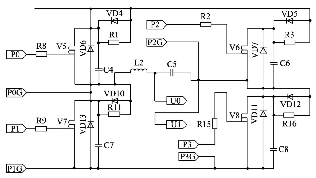
Fig.3 Inverter circuit
In Fig.3,the filter circuit consists of L2 and C5.In addition,each sw itch connects with a snubber circuit in parallel,which is composed of resistance,inductance and diode.It is a typical“RCD” snubber circuit.It can achieve bu ffer in the p rocess of sw itching of the m ain sw itches of the inverter circuit.The control signals which consist of signal UP and DN are from control circuit.The inverter circuitw illgenerate some feedback signals.
1.3 Control circuit
Single chip m icyoco(SCM)is the control core of the section.According to the feedback signals from the inverter circuit,it can control the operation of inverter power supp ly.
In this paper,AT 89C2051 is used as control core,which has fifteen I/O ports,two 16-bit timers,2 KB memory,128 B RAM[3].
It is am icro controller unit(MCU)with high integration and low cost.The circuit of this part is shown in Fig.4.

Fig.4 Control system circuit
In Fig.4,Y 1,Y 2 and BH are feedback voltage signals which are proportional to the current of the inverter circuit.When the control system starts to work,thesignal P3.0 output from SCM w illbe conducted as the input signal of“Watchdog” chip MAX 705.This signal m ust change once within the stipulated tim e for ensuring that“W atchdog” chip can not output the signal“Reset” .If CPU crashes because of interference or other reasons,the signal P3.0 w ill not change.“W atchdog” chip w ill generate the signal“Reset” .CPU w ill reset the operation.The harmonic elim ination PWM control signalsof the inverter are output from P1.7.A fter logical processing and dead-time delay,the signals w ill be turned into tw o driving signals w hich can complement the conduction and have a certain deadtime zone.Then the two driving signals are sent to the d riving chip to control on/off sw itch of the inverter circuit.“SD” of the driving ch ip is contro lled by P3.7.When “SD” is high level“1” ,the d riving chip will be b locked.W hen “SD” is low level“0”,the driving chip can operate.The frequency code inputsignal is input to P1.0.The output signal of P1.4 is conducted as blockade signal of the driving chip through anti-phasing.W hen CPU is in the state of initial reset,it can avoid driving signals appearing high level“1”.When the driving signals all appear high level“1” ,the sw itches will lead to short circuit fault.The fault caused by over vo ltage,under voltage,output over current and short circuit is fed back from auxiliary circuit and protection circuit.The fault passes logic“And”,and then is sent to INT0 of AT 89C2051.Now SCM can send out interrupt requestsignal.
2 Idea and algorithm of harmonic elim ination PWM control
The basic idea of harmonic elimination PWM contro l is described as follows:
The phase of sw itching point of the PWM pulse is conducted as unknow n number.Then through analysis on Fourier series of PWM pulse,the expressions of fundamental component and harmonic compo-nent of output vo ltage w ill be obtained.According to the requirements of fundamental am plitude and harm onic amp litude,an equation w hich is equal to the value of unknown number w ill be established.The sw itching time of each pulse can be acquired by solving the equation.W hen controlling in the light of the sw itching tim e,the fundam ental amp litude and harmonic am plitude of output voltage w ill be expectations.In general,the fundamental am plitude is always selected as an expected non-zero value while the harmonic amp litude is selected as zero value.As a result of equation of harm onic elim ination PWM control,inverter power supp ly w ill not consist of specified low-order harm onic value[4].Supposed that there are N sw itch points in the fourth cycle of PWM waveform which are the inverter output.The phase angle corresponding to each sw itch point is αi(i=1,2,…,N)and0 ≤α1<α2<… <αN≤90°.
According to PWM waveform of the unipolar modulation shown in Fig.5,Fourier seriesof the inverter is described as
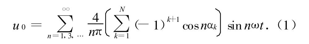

Fig.5 PWM waveform of unipolarm odu lation
According to PWM waveform of the bipolarmodulation shown in Fig.6,Fourier seriesof the inveruer are described as

The number of switching angle“N” in Eq.(2)is odd number w hile in Eq.(3)is even.

Fig.6 PWM waveform of bipolarmodulation
Supposed that the am plitude of the output fundam ental voltage of the inverter is U1,the input direct voltage of bus is U2.If M=U1/U2,then from Eq.(1),the equation of harmonic elim ination w ill be w ritten as

According to Eq.(2),the equation of harmonic elim ination can bew ritten as
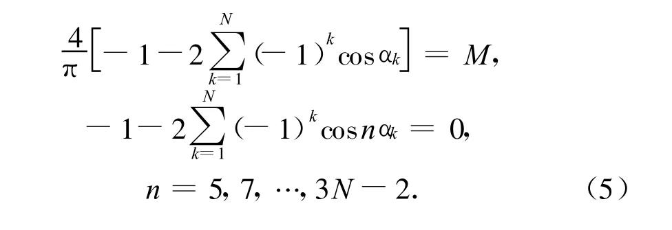
According to Eq.(3),the equation of harmonic elim ination can bew ritten as

New ton iteration method has amount of calculation and local convergence.When selecting inappropriate initial value,solving speed w ill be reduced,even the equation w ill not have convergence.The initial value need to be given again[5-8].
In order to expand the domain of convergence and speed up the convergence[9],the paper introduces hom otopic algorithm to so lve the equation of harm onic elim ination firstly[10,11].Then the result obtained from homotopic algorithm is conducted as the initial value of New ton iterative method.Finally,an accurate solution can be obtained.
Solving Eq.(7)can acquire a group of sw itch angles.They are transformed into a table of timer count pulse of SCM and stored in program mem ory to realize real-time query.
3 Software design
The control software of inverter power supply main ly includes the m ain p rogram,time interrup t service routine and external interrup t service routine.
3.1 Main program
The m ain p rogram initializes operating mode of SCM and reads the output frequency code setting value of inverter power supp ly.When the given frequency changes,the code can also change with it.Now set the frequency change sign.According to the new harmonic elimination PWM sw itching angle data,it can facilitate tim e interrupt service routine to achieve timing and realize the conversion of the driving signals.The flow chart of m ain program is shown in Fig.7.

Fig.7 Flow chart ofmain program
3.2 Time interrupt service routine
Time interrup t service routine can com plete the tim ing of the switching angle data and output of the corresponding d riving signal.It can realize harmonic elim ination PWM contro l strategy.The flow chart of time interrupt service routine is shown in Fig.8.
3.3 External interrupt service routine
External interrupt service routine is responsible for dealing with fault protection of inverter power suppLy.
When fault interrupt request occurs,SCM responds the interrup t and inquires whether fault occurs again.If fau lt exists,the d riving signal w ill be blocked and the fault code w ill be input.The flow ch art of ex ternal interrup t service routine is show n in Fig.9.

Fig.8 Flow chart of time interrupt service routine

Fig.9 Flow chart of external interrupt service routine
4 Results and analysis
Through simulation and debugging,the results are obtained as follows:
The number of sw itching angle N is 10 w hile the initial value is 0.9,thew aveform of output voltage of single-phase inverter power supp ly adopting bipolarm odulation is shown in Fig.10.

Fig.10 Waveform of outputvoltageof single-phase inverter power supp ly adopting bipolar modulation
The number of sw itching angle N is 18 w hile the initial value is 0.9,thew aveform of output vo ltage of single-phase inverter power supp ly adop ting bipolarm odulation is shown in Fig.11.

Fig.11 Waveform of outputvoltageof single-phase inverter power supp ly adopting bipolar modulation
As N increases,the quality of output voltage becomes higher and higher.It is rational that this paper com bined New ton iterationm ethod with homotopic algorithm to solve harm onic equation.
5 Conclusion
In summary,PWM control strategy can ad just the output voltage of inverter Power supp ly conveniently.This paper chooses harmonic elim ination PWM control.Based on this,the whole structure of control system is designed and related software is accomp lised.In addition,high cost-effective CPU as well as safe and reliable com ponents are used to ensure economy and applicability of the power.The new modulation harmonic elim ination PWM control mode which applied to inverter power supp ly can ensure itsadaptability to the fluctuation of the input side of direct voltage.Itw illhave broad application prospects.
[1]ZHANG Jun-li.Im plementation of advanced perm ance inverter power supply.Electronic Engineering&Product W orld,2009,17(7):40-42.
[2]WEIW ei.Research and development trend of sine w ave in inverter Power supply.Elec trical Engineering,2008,9(11):5-7.
[3]ATMEL Corporation.AT89C2051 data sheet.[2012-07-23].http://www.keil.com/dd/chip/2984.htm l.
[4]XIE Yun-xiang,JIANG Lin-zheng.Output filter parameter analysis and design of harmonic elim ination control inverters.Journal of South China University of Techno logy,2004,48(5):1-4.
[5]LIU Hui.New ton iteration method for nonlinear equation solutions and its app lication.Journal of Chongqing Institute of Technology(Natural Science Edition),2007,21(7):95-98.
[6]LIU Jing-fan.Parameter identification for a class of nonlinear systems.W uxi:Jiangnan University,2011,3:19-30.
[7]NI Jian,MA Chang-feng.A new acceleration technique of New ton iterative method for solving non linear equation.Journal of Guangxi Academ y of Science,2010,26(1):1-3.
[8] CHEN Tian-xiong.App lication of New ton iteration m ethod.Journal of Jingchu University of Technology,2010,25(7):42-45.
[9]LIU Hui,HAN Ru-cheng,ZH I Ze-ying.Homotopybased research on harmonic elim ination model in PWM inverter.M odern Electronics Technique,2009,33(8):173-177.
[10]Kato T.Sequential hom otopy-based com putation of multip le solutions for selected harmonic elim ination in PWM inverters.IEEE Transactions on C ircuits and Systtems I:Fundamental Theory and App lications,1999,46(5):586-593.
[11]LI X ia,LIU Jian-ping,YANG A i-m ing.Study and app lication of homotopy new algorithm in inverter harmonic elim ination m odel.Journal of Jiamusi University,2007,25(3):381-384.
猜你喜歡
格言·校園版(2024年10期)2024-06-03 21:42:26
幼兒智力世界(2024年5期)2024-01-01 00:00:00
Chinese Physics B(2023年10期)2023-11-02 08:08:54
詩潮(2019年10期)2019-11-19 13:58:55
天津詩人(2019年3期)2019-11-13 19:29:53
幼兒教育·父母孩子版(2019年6期)2019-10-18 08:11:14
知音·上半月(2018年8期)2018-08-16 03:11:34
東坡赤壁詩詞(2018年3期)2018-07-16 11:39:44
讀者·校園版(2018年13期)2018-06-19 06:20:12
讀寫算(中)(2016年9期)2016-02-27 08:47:36
 Journal of Measurement Science and Instrumentation2013年1期
- Journal of Measurement Science and Instrumentation的其它文章
- Acetonitrile (CH3CN) and methyl isocyanide(CH3NC) adsorption on Pt(111) surface: a DFT study
- Randomized Kaczmarz algorithm for CT reconstruction
- An improved ant colony algorithm and its application in optimal routing problem
- Digital FIR filter design for bio-signal processing system
- Odorant discrimination using functional near-infrared spectroscopy of the main olfactory bulb in rats
- Techniques trend analysis of propagating laser beam quality measurement