
Uplink capacity analysis of single-user SA-MIMO system
2013-01-08 08:26:18DaiJianxinChenMingChungPeiJung
Dai JianxinChen MingChung Pei-Jung
(1National Mobile Communications Research Laboratory, Southeast University, Nanjing 210096, China)(2School of Science, Nanjing University of Posts and Telecommunications, Nanjing 210023, China)(3Institute for Digital Communications, School of Engineering, the University of Edinburgh, Edinburgh EH9 3JL, UK)
As well known, the multiple-input multiple-output (MIMO) system with multiple antennas at both the transmitter and the receiver in a richly scattering environment can significantly increase the capacity of wireless channels without requiring additional power or band-width[1-2]. But the advantages of MIMO systems tend to be lost around the cell edge areas for two principal reasons. The first is the low signal-to-noise ratio (SNR) and inter-cell interference with the low frequency reuse factor. The other is the increase in the signal correlation for different antenna elements. To overcome the problem found in traditional MIMO systems and provide higher data rates, wider coverage and better quality of service (QoS) in the cell edge areas, many new frameworks of multiple antenna systems have been suggested to extend conventional MIMO systems[3-8]. The distributed antenna system (DAS) was investigated in Refs.[3-5] whose basic idea is that all antennas are geographically separated from each other and connected by optical fibers to a central processor where all signals are jointly processed. The downlink performance of single cell and multi-cell MIMO relay networks was analyzed which took into account MIMO technology in fixed relay networks in Ref.[6]. Ref.[7] provided a propagation measurement campaign of a MIMO two-hop relay network in a 5 GHz band in an L-shaped corridor environment with various relay locations and a relay placement estimation scheme to identify the optimum relay location. A brief survey of cooperative MIMO, the basic idea of which is to group multiple devices into virtual antenna arrays to emulate MIMO communications, was provided in Ref.[8].
However, the improvement of performance in the above-mentioned multiple antenna systems comes at the price of increased cost, space and computational complexity due to the individual power constraints of each antenna, the cooperation algorithm and the hardware limitations. In this paper, a new smart antennas-MIMO (SA-MIMO) system with the total power constraint of all antennas is studied. The basic idea of the SA-MIMO is to replace each antenna of traditional MIMO systems with a smart antenna array. Smart antennas, which can suppress the interference coming from different directions by beam-forming and hence can make the cell have a wider coverage and greater user capacity[9-10], are considered as a transmission technology of the single channel current in the 3rd generation of mobile communication systems (3G) standard. And the MIMO technology provides multiple independent transmission channels that can increase system throughput in a long term evolution (LTE) standard. However, a key fact to note is that a richly scattering environment also suffers from high loss. Smart antennas technique improves power gains and increases the SNR which lowers the path loss. Thus, it is of great interest to investigate the combination of the MIMO system and smart antennas in order to ensure the future system a smooth evolution, make the most of existing system resources, avoid extensive redesign of antennas and the feeder system as much as possible, and reduce difficulties of network arrangement and cell-site selection. However, the investigation of the SA-MIMO is rare in the current literature.
In this paper, we propose an SA-MIMO system, which is different from the traditional MIMO systems and other multiple antenna systems, i.e., the DAS and the cooperative MIMO system. For the single-user uplink SA-MIMO system, we first propose an optimization model. Then we investigate the capacity of the single-user uplink SA-MIMO system in some cases. For the general case, it is difficult to derive closed-form solutions of the optimal beam-forming vectors to the capacity optimization problem. This paper presents a suboptimal method for the capacity optimization problem, in which the beam-forming vectors are obtained by maximizing the squared Frobenius norm of the channel matrix.
1 Statement of the Problem
1.1 System model
Consider an uplink SA-MIMO system which is shown in Fig.1. The user transmitter hasNantenna transmitting uplink signals, whose mutual distances are greater than the half wavelength of the carrier wave such that all the transmit channels are independent of each other. At the receiver base station, there areMantenna arrays, each of which hasLelements whose mutual distance is less than half the wavelength. In addition, all theMantenna arrays are mutually so far that their receive channels are independent of each other.

Fig.1 Single-user uplink SA-MIMO system model
Lethmnbe the microscope fading coefficient between then-th transmit antenna and them-th receive antenna array for 1≤m≤Mand 1≤n≤N. The channels are flat Rayleigh fading, i.e.,hmn~CN(0,1), wherex~CN(μ,σ2) means thatxis complex Gaussian distributed with meanμand varianceσ2.


(1)

By stacking the received signals of all the antenna arrays intor={r1,r2,…,rM}T, we have
r=HPs+z
(2)

1.2 Information-theoretic capacity
LetW={ω1,ω2,…,ωM}. If the input signalsis a circularly symmetric complex Gaussian vector with covariance matrixE{ssT}=IN, the instantaneous capacity of the SA-MIMO system for each channel use can be formulated as


H=(hmn〈ωm,amn〉)1≤m≤M, 1≤n≤N
(3)
where ()Hdenotes the complex-conjugate transpose of a vector or matrix.
1.3 Analysis of the capacity
In this section, we investigate the capacity in the case of equal power allocation.
Denoteρ=P/σ2, and letλi(i=1,2,…,M) be the eigenvalues of matrixHHH.
Theorem1In the case that the DOAs from all the transmit antennas are the same in a receive antenna array, i.e.,am1=am2=…=amN=am, and the power is allocated to the transmit antennas equally, the capacity of the SA-MIMO system can be formulated as
(4)
if and only if the optimal beam-forming vector can be written as
(5)
ProofIf the DOAs of all the elements of one smart antenna array are the same, the channel matrixHcan be written as

(6)
where
Moreover, if the power is allocated to the transmit antennas equally, Eq.(3) can be further written as
(7)
Using singular value decomposition (SVD), we have
(8)
(9)
To simplify the rest of the derivations, let
It is obvious thatBis a positive definite Hermitian matrix. Now, from the Hadamard theorem[11], we obtain
(10)
whereAiiandBiiare the diagonal elements ofAandB, respectively. In Eq.(10), there can be equality only ifBis a diagonal matrix. IfAis a diagonal matrix,Bis a diagonal matrix. So Eq.(10) is established only whenAis a diagonal matrix. According to the expression ofA, it can be known that all the diagonal elements are independent. Therefore,
(11)
In Eq.(11), there can be equality if and only ifωiis given by
(12)
And after substitution, the capacity can be written as
if and only if the beam-forming vector is given by Eq.(12).
(13)

Theorem2In the case that the DOAs from different transmit antennas are not the same in a receive antenna array, the upper bound of the capacity of the SA-MIMO system with equal power can be written as
(14)
whereRis the number of singular values of matrixHHH.


s.t. |ωm|F=1m=1,2,…,M
(15)
Letλ1,λ2,…,λRbe non-zero eigenvalues of matrixHHH. From the theorem of the arithmetic and geometric means, we obtain
(16)
with equality when
λ1=λ2=…=λR
(17)
From the Rayleigh-Ritz theorem[11], we obtain
(18)
In Eq.(18), there can be equality whenωmis the main eigenvector ofAm, where
(19)
Namely,
Amωm=λm,maxωm
|ωm|=1, ?m=1,2,…,M
(20)
So the upper bound of the capacity of the SA-MIMO system with equal power can be written as
(21)
with equality when Eqs.(17) and (20) are true.
2 Method for Determining the Beam-Forming Vectors
For the general case, it is difficult to derive closed-form solutions of the optimal beam-forming vectors to the capacity optimization problem (3). Moreover, although the optimal beam-forming vectors can be found numerically, these methods are complicated, and may not be feasible for practical applications. Here, we present a suboptimal algorithm for determining the beam-forming vectors based on the maximum eigenvalue in this paper.
In Ref.[12], an equivalent scaled AWGN channel induced by the space-time block code for complex constellations was given as

(22)


(23)
where

(24)
So we generate the suboptimal beam-forming vectors to solve the capacity optimization problem by the above method.
3 Numerical Results
Monte Carlo simulations are carried out in some cases to compare the capacities of SA-MIMO and conventional MIMO systems. We denote an SA-MIMO system withNtransmit antennas andMreceive antenna arrays, and each array ownsLelements by anN×(M,L) SA-MIMO system.
Fig.2 depicts the ergodic channel capacity of the MIMO system and the SA-MIMO system for various values of SNR withN=2,M=2,L=4 andN=4,M=4,L=4, respectively. It is shown that smart antennas can bring significant capacity gain for the MIMO system without additional spatial degrees of freedom. It is also evident that the upper bound is actually very tight for the considered system.
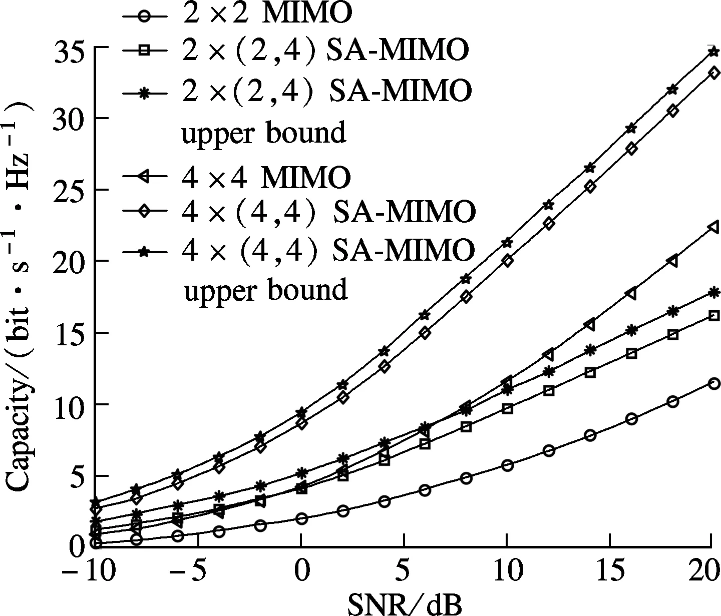
Fig.2 Ergodic capacity comparison between MIMO system and SA-MIMO system
The following simulations are performed by the proposed method for determining the suboptimal beam-forming vectors. All the simulations are performed under the assumption that the transmit power is equally allocated.
NIA denotes an algorithm that the optimal solution of the capacity problem in the SA-MIMO system is obtained by numerical iteration. MEV denotes the method that the optimal beam-forming vectors are obtained by the main eigenvector method.
Case1The same DOAs of one smart antenna
Fig.3 depicts the capacity of the three systems, withN=M=2 andL=8. It is observed that the capacity obtained by the MEV method is equal to the optimal capacity in case 1. This result also validates theorem 2.
Figs.4(a) and (b) illustrate the radiation patterns of the two smart antenna arrays at the receiver for the 2×(2,8) SA-MIMO system for case 1, the beam-forming vectors of which are determined by MEV. It is shown that the pattern gains on the corresponding angles are in the periphery of the peaks, so that the smart antenna will attain a capacity gain.

Fig.3 Ergodic capacity comparison for case 1

Fig.4 Two smart antenna patterns for case 1. (a) The first smart antenna pattern (DOAs are 105°); (b) The second smart antenna pattern (DOAs are 167°)
Case2The different DOAs of one smart antenna
Fig.5 depicts the capacity of the four systems mentioned above, whereN=M=2 andL=8. It is observed that the gap between the capacity obtained by the MEV method and the optimal capacity is small. It indicates that the performance of beam-forming vectors obtained by MEV is acceptable.
Fig.6(a) and Fig.6(b) illustrate the radiation patterns of the two smart antenna arrays at the receiver for the 2×(2,8) SA-MIMO system, the beam-forming vectors of which are determined by MEV. It is shown that the pattern gains on the corresponding angles are in the periphery of the peaks, so that SA will attain capacity gain. Such a gain is due to the use of a smart antenna array, rather than diversity.

Fig.5 Ergodic capacity comparison for case 2

Fig.6 Two smart antenna patterns for case 2.(a) The first smart antenna pattern (DOAs are 8° and 100°, respectively); (b) The second smart antenna pattern (DOAs are 54° and 150°, respectively)
4 Conclusion

Forthcoming work should be focused on analyzing the capacity gain of SA-MIMO systems under the multiple-user case in which the advantage suppressing interference among users can be embodied.
[1]Telatar E. Capacity of multi-antenna Gaussian channels [J].EuropeanTransactionsonTelecommunications, 1999,10(6): 585-595.
[2]Foschini G J, Gans M J. On limits of wireless communications in a fading environment when using multiple antennas [J].WirelessPersonalCommunications, 1998,6(2): 311-335.
[3]Chen Huamin, Wang Junbo, Chen Ming. Outage capacity study of the distributed MIMO system with antenna cooperation [J].WirelessPersonalCommunications, 2011,59(4): 599-605.
[4]Choi W, Andrews J G. Downlink performance and capacity of distributed antenna systems in a multicell environment [J].IEEETransactionsonWirelessCommunications, 2007,6(1): 69-73.
[5]Feng W, Zhao Y F, Zhao M, et al. A novel evaluation method for the downlink capacity of distributed antenna systems [J].IEICETransactionsonCommunications, 2009,E92-B(6): 2226-2230.
[6]Wang Ping, Zu Lijun, Liu Fuqiang, et al. Downlink performance analysis of MIMO relaying networks [J].WirelessPersonalCommunications, 2012,62(3): 729-746.
[7]Lertwiram N, Tran G K, Mizutani K, et al. Performance analysis of MIMO relay network via propagation measurement in L-shaped corridor environment [J].IEICETransactionsonCommunications, 2012,E95-B(4): 1345-1356.
[8]Wang Chengxiang, Hong Xuemin, Ge Xiaohu, et al. Cooperative MIMO channel models: a survey [J].IEEECommunicationsMagazine, 2010,48(2): 80-87.
[9]Andersen J B. Array gain and capacity for known random channels with multiple element arrays at both ends [J].IEEEJournalonSelectedAreasinCommunications, 2000,18(11): 2172-2178.
[10]Dakdouki A S, Tabulo M. On the eigenvalue distribution of smart-antenna arrays in wireless communication systems [J].IEEEAntennasandPropagationMagazine, 2004,46(4): 158-167.
[11]Bellmam R.Introductiontomatrixanalysis[M]. New York: Mcgraw-Hill Book Company, 1970.
[12]Sandhu S, Paulraj A. Space-time block codes: a capacity perspective [J].IEEECommunicationsLetter, 2000,4(12): 384-386.
 Journal of Southeast University(English Edition)2013年1期
- Journal of Southeast University(English Edition)的其它文章
- Factors affecting headway regularity on bus routes
- Effects of carbonaceous conductive fillers on electrical and thermal properties of asphalt-matrix conductive composites
- Fatigue behavior of basalt-aramidand basalt-carbon hybrid fiber reinforced polymer sheets
- Effect of chloride salt concentration on unconfined compression strength of cement-treated Lianyungang soft marine clay
- Response mechanism for widened pavement structure subjected to ground differential settlement
- Flexural behaviors of double-reinforced ECC beams