NUMERICAL SIMULATION OF THE ENERGY DISSIPATION CHARACTERISTICS IN STILLING BASIN OF MULTI-HORIZONTAL SUBMERGED JETS*
CHEN Jian-gang, ZHANG Jian-min, XU Wei-lin, WANG Yu-rong
State Key Laboratory of Hydraulics and Mountain River Engineering, Sichuan University, Chengdu 610065, China, E-mail: chenjg@yeah.net
(Received May 6, 2010, Revised August 16, 2010)
3-D numerical simulation was carried out for the water flow in a stilling basin with multi-horizontal submerged jets by using two different turbulence models, namely, the VOF RNG k?ε and Mixture RNG k?ε turbulence models. The calculated water depth, velocity profile and pressure distribution are in good agreement with the data obtained in experiments. It indicates that the numerical simulation can effectively be used to study the water flow movement and the energy dissipation mechanism. The numerical simulation results show that the turbulent kinetic energy distribution obtained by using the Mixture turbulence model covers a region about 18% larger than that calculated by using the VOF turbulence model, and is in better agreement with the actual situation. Furthermore, the Mixture turbulence model is better than the VOF turbulence model in calculating the air entrainment.
multi-horizontal submerged jets, numerical simulation, VOF method, Mixture method, hydraulic characteristics, stilling basin
1. Introduction
The safety of flood discharging and energy dissipation is a very important issue in hydraulic engineering, especially in cases of high water head and large unit discharge. Many studies were devoted to this problem. Rajanamam[1], Hager[2]and Ohtsu[3]performed experimental studies of the underflow energy dissipation with abrupt drops or symmetric expansions. Katakam[4]studied the characteristics of underflow energy dissipation with abrupt drops and sudden enlargement, and it is found that the required tail-water level to ensure the hydraulic jump can be reduced and the flow pattern in downstream is stable. It is also found that the relative energy loss in the stilling basin is larger than that in the sudden enlargement type basin and the abrupt drop type basin. Zhang et al.[5,6]obtained a theoretical equation for the sequent depth of submerged hydraulic jumps in the stilling basin. They also developed a theoretical equation for the energy dissipation ratio. Deng et al.[7]performed a series of experimental studies of the multi-horizontal submerged jets. It is found that the flow patterns with the change of the tailwater level are quite stable with a large aspect ratio in a stilling basin. Sun et al.[8]found that the contracted orifice width would cause stable flow patterns in the stilling basin, increase the energy loss and reduce the atomization. Huang et al.[9]studied the effect of drop height on the velocity near the slab in stilling basin. Deng et al.[7], Li et al.[10-12], Gao et al.[13], and Yang et al.[14]studied the velocity field in a stilling basin by numerical simulations. It is found that there is no perforative vertical whirl in the stilling basin, the vortex dissociates on the slab and is not fixed on a place.
Multi-horizontal submerged jets are a new typeof energy dissipater. Compared to the ski-jump energy dissipater and the underflow energy dissipater, they have features of weak atomization, high energy dissipation ratio and stable flow pattern. Due to their complex vortex structure and strong air entrainment in the stilling basin, it is hard to simulate the structure and intensity of the vortex by a routine test method, however, the numerical simulation can provide a good supplement to physical model tests and be used to obtain the detailed hydraulic characteristics of the velocity field.
With the development of the computer technology, the application of turbulence models and the improvement of numerical methods, the numerical simulation plays an important part in studying the problems of hydraulics. Studies by Karim and Mali[15], Xu et al.[16], Lu and Li[17]and Ai and Jin[18]show that the k?ε two-equation turbulence model is an useful tool in simulating this complex water flow. In this study, the characteristics of the hydraulic jumps in a stilling basin of multi-horizontal submerged jets are studied by using VOF RNG k?ε and Mixture RNG k?ε turbulence models, for a further understanding of the characteristics of energy dissipation and air entrainment in the stilling basin of multi-horizontal submerged jets.
2. Numerical model and boundary conditions
2.1 VOF turbulence model
Although the flow pattern is very complex in a stilling basin of multi-horizontal submerged jets, the Navire-Stokes equation can still give a precise mathematical description of multi-horizontal submerged jets. Today, a numerical simulation of 3-D free surface flows has become computationally affordable[19,20]. The RNG k?ε model is used to calculate the hydraulic parameters of the flows through the energy dissipaters. This model can very well simulate the anisotropy of high-speed jets. The governing equations for the VOF turbulence model are as follows
Continuity equation:
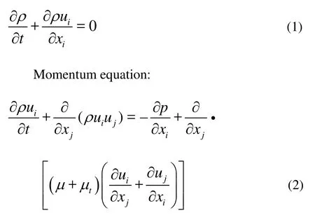
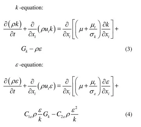
where ρ and μ are the density of the averaged volume fraction and the molecule viscosity coefficient, respectively. μtis the turbulent viscosity coefficient, obtained through the turbulent kinetic k and the turbulent dissipation rateε as
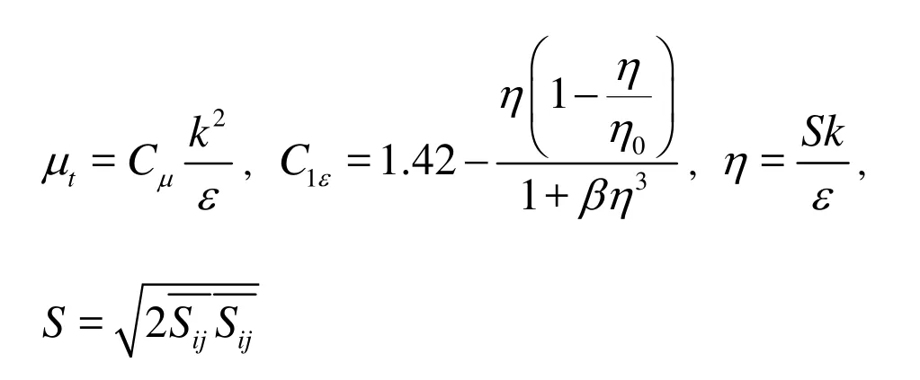
In the tensor expression, xirepresents x, y, z and ui, u , v , w , where i=1,2,3 , i andj are used as the summation subscripts. The general model constants of the equation include, η0=4.38, β =0.012, Cμ=0.085, C2ε=1.68, σk=0.7179, σε=0.7179.
2.2 Mixture turbulence model
The Mixture model is a simplified multiphase flow model, which is used to simulate the flow of multiphases with different velocities. It is assumed that the balance is maintained in short-range spatial scales. The model includes the mixed phase momentum equation, continuity equation and energy equation, as well as the relations between the volume fractions of different phases and about the slip velocity. The Mixture turbulence model differs from the VOF turbulence model in the following aspects. First, the Mixture model allows an inter-penetration among different phases, that is, the volume fraction takes a value from zero to one in the same control volume. Second, it allows a slip velocity betweendifferent phases. The governing equations are as follows
Continuity equation:
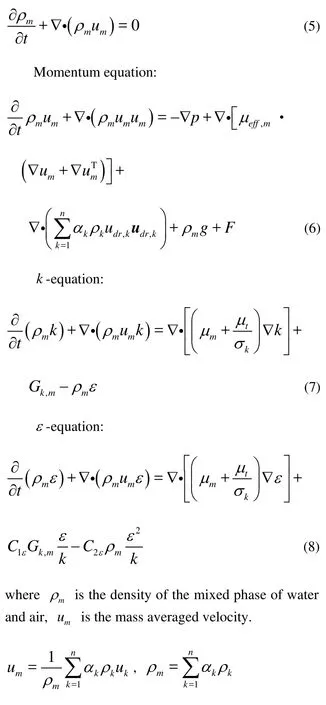
where ρkis the density of k phase, ukis the mass averaged velocity of k phase,αkis the volume fraction of k phase, F is the body force, g is the acceleration of gravity, μeff,mis the coefficient of the virtual viscosity, and μeff,m= μl,m+μt,m, and udr,kis the drift velocity of kphase.
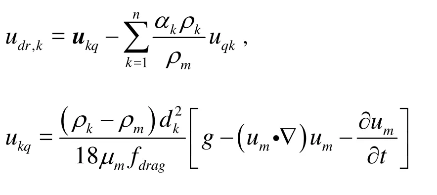
where ukpis the relative slip velocity betweenk phase and the first phase ( q phase),fdragis the resistance coefficient.
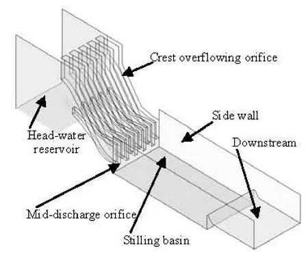
Fig.1(a) Numerical simulation region
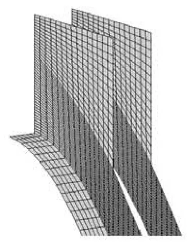
Fig.1(b) Mesh of crest overflowing orifice
2.3 Boundary conditions
The numerical simulation was carried out for the stilling basin of multi-horizontal submerged jets, as is in a practical project. The drop elevations of crest overflowing orifices and mid-discharge orifices are 261.0 m and 253.0 m, respectively, namely, the drop heights are S1=16.0 m and S2=8.0 m, for crest overflowing orifices and mid-discharge orifices, respectively. The flood discharging section includes 6 crest overflowing orifices and 5 mid-discharge orifices, and these orifices are alternately arranged. The stilling basin is 228.0 m long and 108.0 m wide. The elevation of the stilling basin slab is 245.0 m. The calculation region and the computing grid are shownin Fig.1. The numerical simulation covers the flood discharging section, the head-water reservoir, the stilling basin and the downstream reach. The identical computing grid is used in the numerical simulation in this article, and the details of the numerical simulation are shown in Table 1.

Table1 Details of the numerical simulation
(1) Inflow boundary: The variable values on the inflow boundary must be given. The velocity of the inflow is calculated according to the discharge and the water level, and it is given on the inflow boundary.
(2) Outflow boundary: The outflow boundary conditions are given on the exit of the calculation region, based on the uniform flow conditions.
(3) Wall boundary: Using the wall-function method.
(4)Computing grid: The identical grid is used in the numerical simulation for two different turbulence models.
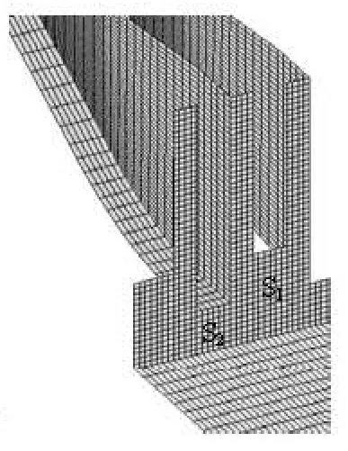
Fig.1(c) Mesh of mid-discharge orifice
3. Numerical simulation results and analyses
3.1 Water surface profile
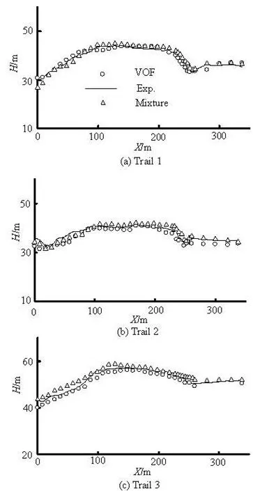
Fig.2 Water surface profile calculated and measured
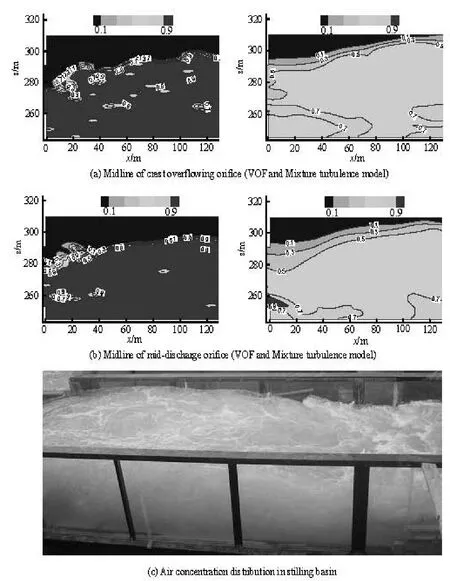
Figure 2 shows the simulated and measured results of the water surface profile of the multi-horizontal submerged jets in a stilling basin. The origin of the coordinate system is set at the intersection of the drop and the centerline of the slab of the stilling basin, where X is the distance from measuring points to the drop, H is the water depth, Ystands for the distance from measuring points to the midline of the stilling basin. VOF stands for the numerical results obtained by using the VOF turbulence model, Mixture stands for the numerical results obtained by using the Mixture turbulence model and Exp. stands for experimental results. It can be seen from Fig.2 that the computed water surface profile agrees very well with that measured from the physical model. In the experiments, it can be seen from the cross section that the water surface breaks in the stilling basin, therefore, the water depth near the sidewall is measured in detail. The aerated water in the foreside of the stilling basin is strongly turbulent and the free water surface fluctuates greatly and randomly, which makes it difficult to identify the testing point exactly, which is the main reason why the water surface profile in the foreside of the stillingbasin varies greatly. At the end of the stilling basin, the water flow is smooth and the wave is small, thus the measured and computed values see little difference. The water depth gradient is very large in the foreside of the stilling basin in Trail 1 and Trail 3, while the water depth is very flat in Trail 2 and the water surface profile has a relation with the water depth at the end sill of the stilling basin.
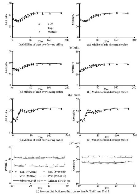
Fig.3 Pressure distribution calculated and measured
3.2 Pressure distribution
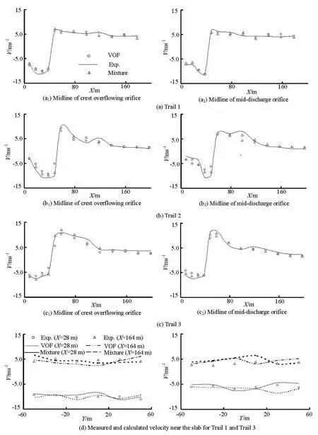
Fig.4 Measured and calculated velocities near the slab
The calculated and measured pressure distributions on the slab of the stilling basin are shown in Fig.3, where Y is the distance from measuring points to the centerline of stilling basin. It can be seen from Fig.3 that the calculated values agree very well with the measured ones except in the foreside of the stilling basin, where there is a small difference. Timeaveraged pressure values see little difference when X<80 min Trail 1 and Trail 2, while the measured and calculated pressures keep consistent when X>80 m. There is a great pressure gradient on the slab of the stilling basin when 10 m Fig.5 Distributions of turbulent kinetic energy and turbulence dissipation rate for Trail 3 3.3 Velocity near the slab in stilling basin The measured and calculated velocities near the slab in the stilling basin are shown in Fig.4. The velocity measuring points are about 0.5 m from the slab of the stilling basin. It can be seen from Fig.4 that the calculated values agree well with the measured ones. The velocity near the slab in the stilling basin decays fast, the points of the maximum positive and negative velocities are almost at the same point in the stilling basin and the velocity distribution has the same trend. However, there is a little error in the numerical values. The measured and calculated velocities see a little difference when X<60 m in Trail 2 and Trail 3. The main reason is that during the experiments, the water in the stilling basin is severely turbulent and the location and size of the maximum velocity are not fixed, while the experimental value is the instantaneous maximum at a fixed point. 3.4 Turbulence flow characteristics Fig.6 Air entrainment distribution for Trail 3 The distributions of the turbulent kinetic energy and the turbulence dissipation rate obtained by using the VOF RNG k?ε and Mixture RNG k?ε turbulence models are shown in Fig.5. It can be seen from Fig.5 that the turbulent kinetic energy takes the maximum on the foreside of the stilling basin, then gradually declines along the slab of the stilling basin. Near the foreside of the stilling basin, the flow is strongly turbulent and most of the energy is dissipated. The energy dissipation is very weak at the end of the stilling basin. It can be seen from the transverse section that there is a high efflux velocity at the core of the jet flow, while the velocity gradient is small. Turbulent kinetic energy at the core of the jet flow is smaller than that at the other shear area. Around the jet flow, the flow velocity decreases but the velocity gradient increases, thus the turbulent kinetic energy is very large. The turbulent kinetic energy distributions as obtained by using the VOF and Mixture turbulence models cover an region of 0 m 3.5 Air concentration The air concentration distributions obtained by using the VOF RNG k?ε and Mixture RNG k?ε turbulence models in Trail 3 are shown in Fig.6, where the blue color stands for air and the red for water. The contours of the air concentration obtained by using the VOF turbulence model are densely distributed on the water surface, while the air concentration is small in the water body and is almost equal to zero near the slab and the side wall of the stilling basin. At the same time, there are some gas pockets of different sizes in the water body, which does not very well agree with the practical situation of the water flow movement. The air concentrationobtained by using the Mixture turbulence model is about 20% on average near the slab and the side wall of the stilling basin, as in agreement with the practical situation of the water flow movement. The Mixture model allows the interpenetration among different phases, namely, the volume fraction takes a value ranging from zero to one in a control volume, so the results obtained by using the Mixture turbulence model are better than those obtained by using the VOF turbulence model. The Mixture turbulence model can simulate the distribution of the air concentration in a turbulent flow, however, the two methods can not simulate the size of the air bubbles. During the experiments, it can be seen that the high-speed flow is strongly turbulent in the stilling basin and the water body has a certain air concentration, which can be calculated by the Mixture turbulence model with better agreement with the practical situation as compared with that calculated by using the VOF turbulence model. The VOF turbulence model has limitations when it is applied to strong air entrainment flows in predicting the air concentration. The numerical simulation is carried out for the stilling basin of multi-horizontal submerged jets, as is in a practical project with the final scheme. The characteristics of the hydraulic jump in a stilling basin of multi-horizontal submerged jets are studied by using VOF RNG k?ε and Mixture RNG k?ε turbulence models in this article, and the numerical simulation results are verified by a series of model experiments. The conclusions are as follows: (1) 3-D numerical simulations are carried out for the water flow in a stilling basin of multi-horizontal submerged jets by using two different turbulence models, that is, the VOF RNG k?ε and the Mixture RNG k?ε turbulence models. The calculated results, such as water depth, velocity profile and pressure distribution, are in good agreement with those obtained by experiments. It indicates that the two turbulence models are valid. (2) The numerical results of the two turbulence models give a detailed picture of the mainstream decay process, vortex patterns, turbulence intensity and its distribution. The hydraulic characteristics and energy dissipation processes can be well described and the numerical simulation results can provide a good supplement to the results obtained in model experiments. (3) The turbulent kinetic energy distribution calculated by using the Mixture turbulence model covers a region about 18% larger than that calculated by using the VOF turbulence model on the average. Hence, the energy dissipation region calculated by using the Mixture turbulence model agrees better with the practical situation of the water flow movement. (4) The air concentration distribution calculated by using the Mixture turbulence model agrees very well with that in the stilling basin of multi-horizontal submerged jets, it indicates that the Mixture turbulence model is better than the VOF turbulence model in calculating the air concentration. [1] RAJANATNAM N., SUBRAMANYA K. Hydraulic jumps below abrupt symmetrical expansions[J]. J. Hydr. Div. ASCE, 1968, 94(2): 481-503. [2] HAGER W. H. B-Jumps at abrupt channel drops[J]. Journal of Hydraulic Engineering, ASCE,1985,111(5): 861-866. [3] OHTSU I, YASUDA Y. and ISHIKAWA M. Submerges hydraulic jump below abrupt expansion[J]. Journal of Hydraulic Engineering, ASCE,1999, 125(5): 492-499. [4] KATAKAM V. Spatial B-jump at channel enlargements with abrupt drop[J]. Journal of Hydraulic Engineering, ASCE, 1998, 124(6): 643-646. [5] ZHANG Jian-min, YANG Yong-quan and XU Wei-lin et al. Theory of multi-horizontal submerged jets and experimental investigation[J]. Advances in Nature Science, 2005, 15(1): 97-102(in Chinese). [6] ZHANG Jian-min, WANG Yu-rong and YANG Yong-quan et al. Energy dissipation and hydraulics characteristics of multi-horizontal submerged jets[J]. Advances in Water Science, 2005, 16(1): 18-22(in Chinese). [7] DENG Jun, XU Wei-lin and ZHANG Jian-min et al. A new energy dissipator- multi-horizontal submerged jets[J]. Science in China Series E: Technological Sciences, 2009, 39(1): 29-38(in Chinese). [8] SUN Shuang-ke, LIU Hai-tao and XIA Qing-fu et al. Study on stilling basin with step-down floor for energy dissipation of hydraulic jump in high dams[J]. Journal of Hydraulic Engineering, 2005, 36(10): 1188-1193(in Chinese). [9] HUANG Qiu-jun, FENG Shu-rong and LI Yang-nong. Experimental study on energy dissipation characteristics of multi-horizontal submerged jets[J]. Chinese Journal of Hydrodynamics, 2008, 23(6): 694-701(in Chinese). [10] LI Yan-ling, HUA Guo-chun and ZHANG Jian-min et al. Analysis on energy dissipation of the single-lever with multi-strand and multi-lever with multi-strand horizontal submerged jets[J]. Journal of Hydrodynamics, Ser. A, 2006, 21(1): 26-31(in Chinese). [11] LI Yan-ling, HUA Guo-chun and ZHANG Jian-min. Factors affecting the hydraulic characteristics of horizontal submerged jets[J]. Advances in Water Science, 2006, 17(6): 761-766(in Chinese). [12] LI Yan-ling, YANG Yong-quan and HUA Guo-chun et al. Experimental study on multi-horizontal submerged jets[J].Journal of Sichuan University (Engineering Science Edition), 2004, 36(6): 32-36(in Chinese). [13] GAO Peng, YANG Yong-quan and DENG Jun et al. Investigation on complex flow pattern of multi-submerged jets into plunge pool[J]. Journal of Sichuan University (Engineering Science Edition),2006, 38(5): 70-75(in Chinese). [14] YANG Zhong-chao, DENGJun and YANG Yong-quan et al. Numerical simulation of multiple submerged jets on multilevel dicharged into plunge pool[J]. Journal of Hydraulic Engineering, 2006, 38(5): 70-75(in Chinese). [15] KARIM O. A. K., MALI K. H. M. Prediction of flow patterns in local scour holes caused by turbulent water jets[J]. Journal of Hydraulic Research, 2000, 38(4): 279-287. [16] XU Wei-lin, LIAO Hua-sheng and YANG Yong-quan et al. Numerical simulation of 3-D turbulent flows of plunge pool and energy dissipation analysis[J]. Journal of Hydrodynamics, Ser. A, 1996, 11(5): 561-569(in Chinese). [17] LU Lin, LI Yu-cheng. Numerical simulation of turbulent free surface flow over obstruction[J]. Journal of Hydrodynamics, 2008, 20(4): 414-423. [18] AI Cong-fang, JIN Sheng. Three-dimensional free surface flow model for simulating water wave motions[J]. Chinese Journal of hydrodynamics, 2008, 23(3): 338-347(in Chinese). [19] WANG Kun, JIN Sheng and LIU Gang. Numerical modeling of free-surface flows with bottom and surface-layer pressure treament[J]. Journal of Hydrodynamics, 2009, 21(3): 352-359. [20] WU Jian-hua, AI Wan-zheng. Flows through energy dissipaers with sudden reduction and sudden enlargement forms[J]. Journal of Hydrodynamics, 2010, 22(3): 360-365. 10.1016/S1001-6058(09)60110-4 * Project supported by the National Key Basic Research Program of China (973 Program, Grant No. 2007CB714105), the Science Foundation of Ministry of Education of China (Grant No. 2008108111) and the Program for New Century Excellent Talents in University (Grant No. NCET-08-0378). Biography: CHEN Jian-gang (1982-), Male, Ph. D. Candidate ZHANG Jian-min, E-mail: jmzhangscu@263.net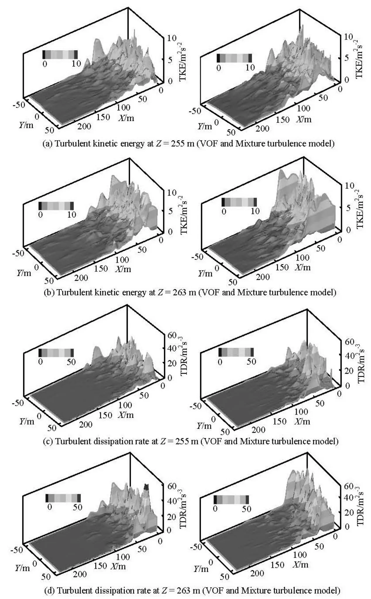
4. Conclusions

