
SEEPAGE ABILITY OF HIGH-PRESSURE HOT COMPOSITE FOAM IN POROUS MEDIA*
2010-05-06 08:05:08WANGKeliang
水動力學(xué)研究與進(jìn)展 B輯 2010年1期
WANG Ke-liang
The Key Laboratory of Enhanced Oil and Gas Recovery of the Ministry of Education, Daqing Petroleum Institute, Daqing 163318, China
College of Civil and Environmental Engineering, University of Science and Technology Beijing, Beijing 100083, China, E-mail: wangkl0608@126.com
LIANG Shou-cheng
The Key Laboratory of Enhanced Oil and Gas Recovery of the Ministry of Education, Daqing Petroleum Institute, Daqing 163318, China
YUAN Xin-qiang, CHEN Jin-feng
The Second Oil Production Company of Daqing Oilfield Company Ltd., Daqing 163414, China
(Received October 13, 2009, Revised December 8, 2009)
SEEPAGE ABILITY OF HIGH-PRESSURE HOT COMPOSITE FOAM IN POROUS MEDIA*
WANG Ke-liang
The Key Laboratory of Enhanced Oil and Gas Recovery of the Ministry of Education, Daqing Petroleum Institute, Daqing 163318, China
College of Civil and Environmental Engineering, University of Science and Technology Beijing, Beijing 100083, China, E-mail: wangkl0608@126.com
LIANG Shou-cheng
The Key Laboratory of Enhanced Oil and Gas Recovery of the Ministry of Education, Daqing Petroleum Institute, Daqing 163318, China
YUAN Xin-qiang, CHEN Jin-feng
The Second Oil Production Company of Daqing Oilfield Company Ltd., Daqing 163414, China
(Received October 13, 2009, Revised December 8, 2009)
The technology of hot composite foam displacement refers to the injection of high-temperature flue gas and foaming and stabilizing agent into wells with a certain concentration, and after meeting the formation water, a composite foam system is formed in the reservoir. This foam displacement technology involves thermal function and so is related to nitrogen, carbon dioxide and foam flooding characteristics. After analyzing seepage flow law of hot composite foam system, seepage flow experiment of composite foam under high pressure was conducted, and seepage flow ability of hot composite foam in porous media was investigated. In the experiment, surfactant HY-3 was chosen as the foaming agent and hot flue gas was chosen as the foaming gas, and high-pressure hot foaming apparatus was employed in experiments. The experimental results indicate that the surfactant HY-3 could form stable foam in porous media, and the foam has strong ability of plugging. It is concluded that the sealing performance of foam is improved with increasing permeability and resistance coefficient and with incresing injection rate and foam strength. After foam injection, sealing characteristics of heterogeneous cores is better than that of homogeneous cores. The foam pressure has a process of transmission in porous media. In this process, with the increase of injection volume, pressure from the inlet to the outlet increases gradually, which indicates that stable foam has been formed inside the core.
composite foam, surfactant HY-3, seepage flow under high pressure, porous media
1. Introduction
In recent years, foam flooding has been paid increasing attention due to its unique properties of seepage and oil displacement[1-4]. Foam flooding cannot only improve macro-sweeping volume significantly, but also improve micro-displacement efficiency[5,6], so it is a more promising EOR technology[7]. The technology of hot composite foam displacement refers to the technology that high temperature flue gas and foaming and stabilizing agent with a certain concentration are injected into oil wells, so that a composite foam system is formed. It isof great importance to understand the foam flooding characteristics.
In the past, a lot of research on flooding and seepage flow ability of N2, natural gas and CO2foam was carried out[8-10]. In this article, hot flue gas foam is studied, and the foaming agent is hot flue gas which has advantage of thermal, N2and CO2foam displacement. In addition, because of the unique properties of foam system, seepage flow ability is closely related to pressure. Therefore, in this article, backpressure valve was installed at the outlet of the core to control system backpressure to research seepage flow ability of foam system in high-pressure condition.
2. The mathematical mode of hot composite foam flooding
In the fluid mode of composite hot foam, a seven-component fluid model was established, which consists of surfactant, polymer, nitrogen, carbon dioxide, foam, oil and water. The mathematical model of high-temperature foam flooding is a multi-phase and multi-component one based on the established model of thermal recovery[11,12].
2.1 Mass conservation equations
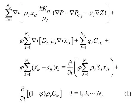
where ρ is the density, k the absolute permeability,xIJthe mole fraction of component I in phase J,μ the fluid viscosity, P the reservoir pressure, Pcthe capillary pressure, γ the specific gravity, φ the porosity, q the source/sink term,S the saturation,J the type of fluid phase, I the class of component, SI′kthe generation coefficient of component J in the chemical reaction k,SIkthe loss coefficient of component I in the chemical reaction k, rkthe reaction velocity in the reaction k. When an aqueous solution of foam transports in porous media, the dynamic adsorption process can be described by the following equation[13]:
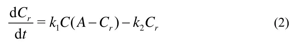
where Cris the surfactant concentration adsorbed on the medium surface, C the surfactant concentration in the aqueous solution,A the maximum adsorption concentration on the core surface, k1the adsorption rate constant, k2the desorption rate constant. Equation (2) is the Langmuir isotherm adsorption equation when the balance between adsorption and desorption is achieved.
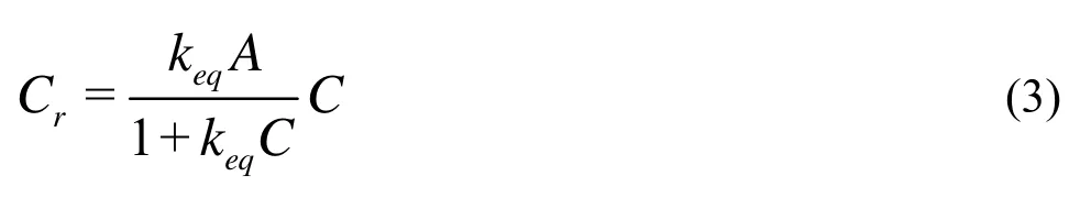
where keq=k1/k2is the constant of equilibrium adsorption.
In the process of foam flooding, it is found that foam agent has thermal decomposition effect at a certain temperature. Generally the thermal decomposition of foam complies with the first order reaction kinetics.
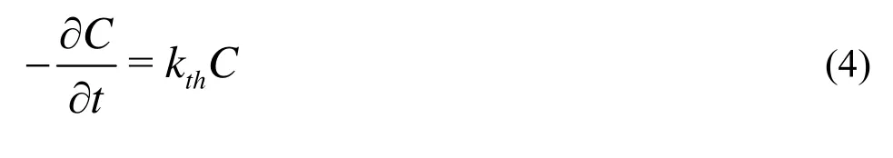
where kthis the thermal decomposition rate constant which is a function of temperature and pH value of solution, described by the following formula:
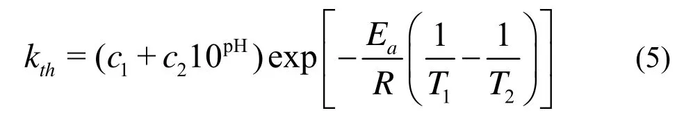
where c1and c2are experimental constants at the reference temperature T2, Eais activation energy.
2.2 Equations of conservation of energy and auxiliary equation
The equation of conservation of energy reads
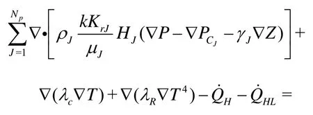
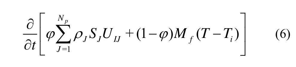
where H is the heat function, U the intrinsic energy, λcthe formation thermal conductivity, λRthe thermal emissivity, T the temperature,the enthalpy change due to injection and output of fluid,HLthe heat loss rate flowed into the top and bottom of the reservoir,Mfthe heat capacity of reservoir rock.
2.3 Influence of foam on the relative permeability
According to Stone theory, in the hydrophilic rocks, the water permeability is related with water saturation, and the gas permeability is related with gas saturation, while the oil permeability is dependent on both permeability water and gas permeability.
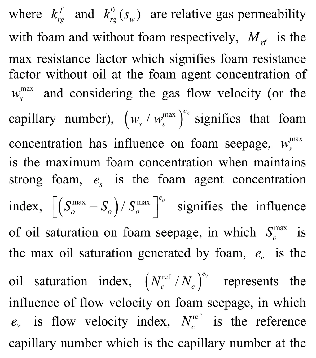
Based on experiment results, the foam mobility is determined by surfactant concentration, gas flow velocity (or capillary number), oil saturation and so on. It can be described by the following formula: referred flow velocity.
3. High-pressure seepage flow experiments of hot composite foam in porous media
3.1 Hot composite foam seepage flow experiments in single long core
3.1.1 Experimental materials
Man-made long core was selected, the core size was 0.045 m× 0.045 m× 0.3 m. The component of flue gas was 85% N2and 15% CO2. The salinity of formation water was 4300 mg/L. The foaming agent was Surfactant HY-3[14].
3.1.2 Experimental procedures
(1) The core was evacuated, saturated with formation water, and then the permeability was measured with water.
(2) The booster pump was used to increase the backpressure to 20 MPa.
(3) The core was put into a core holder, and maintained 8 h at a temperature of 70oC. In high-pressure condition, foam was injected until stable foam appeared at the outlet of the core. Gas-liquid ratio of foam was 1:1.
3.1.3 Experimental results
Seven experiments of foam high-pressure seepage flow were carried out[15,16], and the results are shown in Table 1.
(1) Effect of different permeabilities of cores on foam seepage flow ability
To compare with programs 1 and 2 in Table 1, the high permeability core has lower differential pressure, whereas it has a larger resistance factor. It shows that the foam plugging effect is more appreciable with higher permeability,. This is due to the larger pore in the high permeability core and the stronger foaming ability. Furthermore, in the process of increasing the radius of the capillary, the structure of foam changes from single-chain one into increasing bundle one, so that the stability of the foam and its viscosity increase gradually. With the increase of injection rate, a stronger foam plug could be formed, while it has a larger resistance coefficient. This is the reason why high permeability layers could be plugged in the process of foam flooding.
(2) The effect of different gas-liquid ratio on foam seepage flow ability
Through comparing programs 3, 4, 5 and 6 in Table 1, it is found that under high-pressure condition, gas-liquid ratio has influence on foam seepage flow ability. The foam seepage resistance coefficient VS. gas-liquid ratio curve is shown in Fig.1. It can be seen that the greater foam seepage resistance increases with increasing gas-liquid ratio. The trend of curve shows that if the gas-liquid ratio is higher than 1:1, the slope of the curve reduces gradually, and the growth rate of resistance coefficient reduces. Therefore it can beconcluded that stable foam in the rock can be formed at the gas-liquid ratio of 1:1.
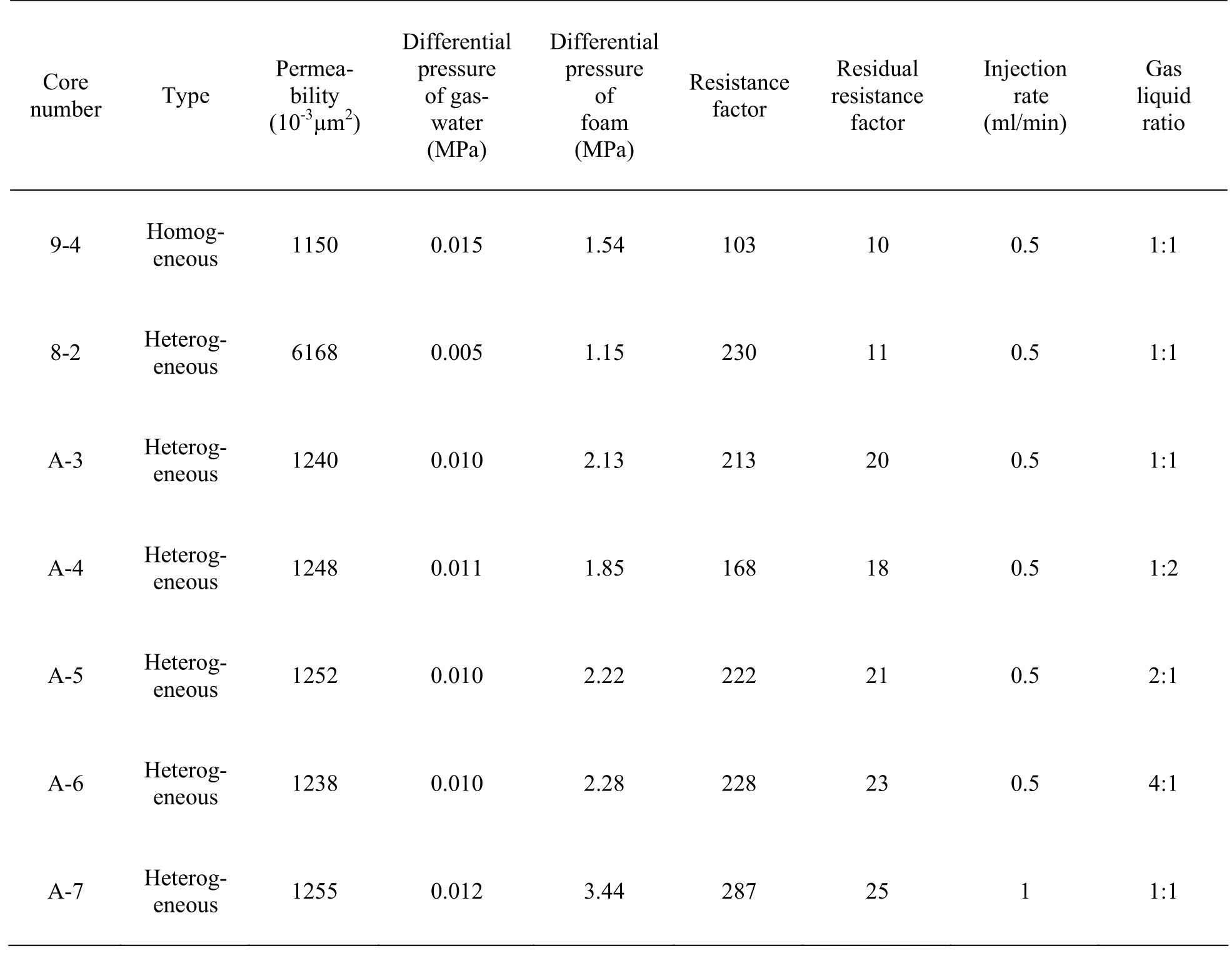
Table 1 Experiment results

Fig.1 Relationship between foam seepage resistance factor and gas-liquid ratio
(3) The effect of types of cores on foam seepage flow ability
The comparison of programs 1 and 3 shows that if the difference in permeability is not significant, then the sealing characteristics of heterogeneous cores are better than that of homogeneous cores. The reason is that the pores of heterogeneous cores are less uniform than those of homogeneous cores. High permeability layers have larger pores, so that injected foam enters high permeability layers and large channel first, and the stronger plugging ability is generated. With the increase of injection volume, foam plug is formed gradually. Consequently, it increases seepage resistance. Because of smaller pores and weaker foaming ability in low-permeability layers, later injected fluid will enter low permeability layers evenly. Foam in the core plays a role in sealing large channels, not small ones. This function increases injection pressure, so that it has better plugging effect.
(4) The affect of different injection rate on foam seepage flow ability
The comparison between programs 3 and 7 in Table shows that the injection rate has some influent on foam plugging ability. The resistance coefficient increases with increasing injection rate. The reason is that the forming of foam needs to a certain amount of energy. If the injection rate is lower, then the capacity of flowing is smaller and plugging ability is weak, and vice versa. The strong ability of flow can overcome power of foaming. Thus foaming ability of the system is enhanced greatly, the performance of foam system is improved and plugging ability of formation isincreased, which results in increasing flow differential pressure of foam.
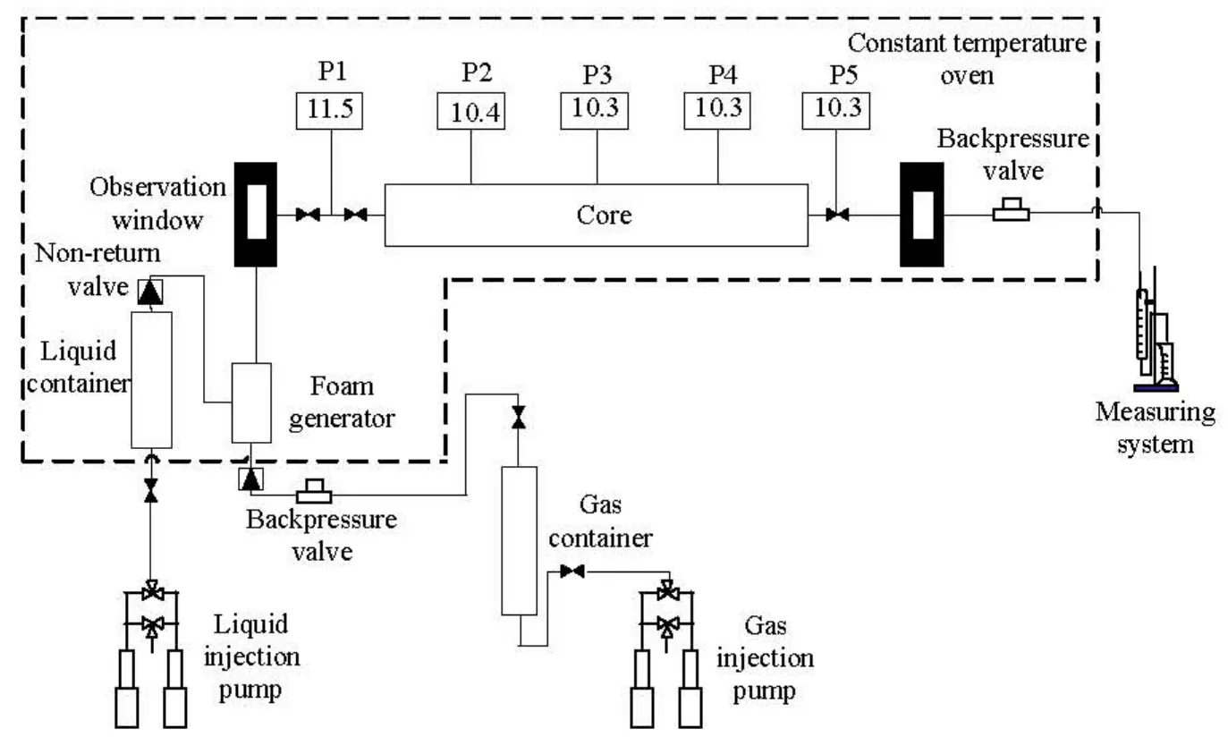
Fig.2 Experimental process
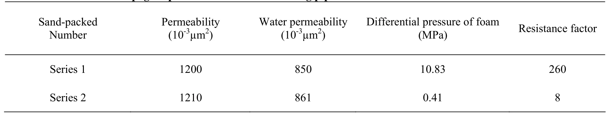
Table 2 Results of foam seepage experiment in serial sand filling pipes
3.2 The hot composite foam seepage flow experiment
in series sand-packed pipes
The model contains four Φ 0.38 m× 0.75 m sand-packed pipes. The core permeability is 1.2 μm2. Foam and flue gas seepage flow experiments were carried out. 5 sensors were installed every 0.75 m to measure pressure drops, which was recorded by computer automatically. The pressure sensors No. 1 and 5 measure the pressure drops at the inlet and outlet of the model respectively, while No. 2, 3, 4 measure pressure drops inside the sand-packed model. Experimental process is shown in Fig.2.
Surfactant HY-3 was used as the foaming agent, the surfactant concentration was 0.3%, the gas-liquid ratio was 1:1, the injection rate was 1 ml/min (1 m/d), and the backpressure at the outlet was 10 MPa. The results are shown in Table 2 and Figs.3-4.
Table 2 shows that when flue gas was injected, the maximum differential pressure was only 0.41 MPa and resistance coefficient was 8. But when foam was injected, the maximum differential pressure reached 10.83 MPa, and resistance coefficient was 260. This indicates that stable foam has been formed in porous media.
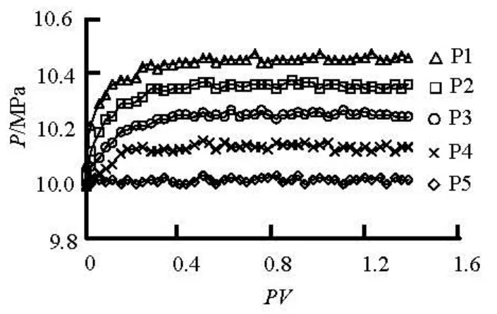
Fig.3 Relationship between flue gas injection PV number and pressure

Fig.4 Relationship between foam injection PV number and pressure
Figures 3 and 4 show that when flue gas was injected, the initial pressures at the 5 pressure points were the same. With the increase of injection volume, the increase of pressure at each point was not significant, and there existed a certain fluctuation. The total pressure drop was only about 0.4 MPa.
When foam was injected, the initial pressures at the 5 pressure points were also the same. With the increase of injection volume, pressures at the 5 pressure points increased in turn. The pressures increased from point 1 to point 4 in sequence. If 0.02 PV foam was injected, pressure in the sensor No.1 pressure-point began to increase. When the injection reached 0.06PV, the pressure of foam spread to the pressure-point 2. When 0.12PV foam was injected, it spread to the pressure-point 3. When 0.16PV foam was injected, the pressure spread to the pressure-point 4. Finally, as the injection volume reached 0.2PV, the pressure of foam began to be stable. The pressure differences between every two adjacent pressurepoints were the same, about 2.5 MPa. This indicates that in the process of plugging, there exists a process of pressure transmission. In the process of transmission, with the increase of injection volume, pressure increases from the inlet to the outlet in sequence. This indicates that stable foam has been formed, and the pressure gradient within the model is the same.
4. Conclusion
In high-pressure condition, the foam seepage resistance increases with increasing gas-liquid ratio. But if gas-liquid ratio was greater than 1:1, the seepage resistance does not change significantly. In high-pressure condition, for different types of cores, the resistance coefficient increases with increasing permeability, and the better sealing ability of foam was. For the same permeability, the sealing characteristics of heterogeneous cores are better than those of homogeneous cores. with increasing injection rate, the foam becomes stronger and the sealing ability of foam better. The high foam resistance coefficient in the sand-packed pipe indicates that foam had strong sealing ability in porous media. There exists a process of transmission of foam pressure in porous media during foam sealing. In this process, with the increase of injection volume, pressure increases gradually from the inlet to the outlet, which indicates that stable foam has been formed inside the cores.
[1] QUOC P. N., ALEXANDER V. A. and PACELLI L. Z. Experimental and modeling studies on foam in porous media: A review[C] . SPE 58799. Lafayette, Louisiana, USA, 2000, 110-121.
[2] WANG Yu-dou, SHANG Yong-tao. Study on the effect of foam on gas-liquid relative permeability[J]. Journal of Oil and Gas Technology, 2008, 30(4): 146-149( in Chinese).
[3] WANG Qi-wei, GUO Ping and ZHOU Guo-hua et al. Experimental research on low-tension foam flooding system without alkali[J]. Special oil and Gas reservoirs, 2003, 10(3): 79-83(in Chinese).
[4] VASSENDEN F., HOLT T. Foam propagation in the absence and presence of oil[C]. SPE 59284. Tulsa, Oklahoma, USA, 2000, 81-90.
[5] LI Xue-song. Laboratory study on foam combination flooding system without alkali and low interfacial tension[J]. Journal of Oil and Gas Technology, 2009, 31(1): 130-133(in Chinese).
[6] LV Guang-zhou, ZHANG Jian-qiao and SUN Ye-heng. Research on numerical simulation of N2foam displacment[J]. Journal of Hydrodynamics, Ser. A, 2005, 17(4): 531-537(in Chinese).
[7] LIAO Guang-zhi, LI Li-zhong and KONG Fan-hua et al. Technology of conventional foam oil displacement[M]. Beijing: Petroleum Industry Press, 1999(in Chinese).
[8] LIU Y., GRIGG R. B. and BAI B. Salinity. pH, and surfactant concentration effects on CO2-foam[C]. SPE 93095. Woodlands, Texas, USA, 2005, 111-121.
[9] LIU Y., GRIGG R. B. and SVEC R. K. CO2Behavior influence of temperature, pressure, and concentration of surfactant[C]. SPE 94307. Oklahoma City, Oklahoma, USA, 2005, 210-212.
[10] WANG Lu-shan, CAO yan-bin and YU Tian-tian. Effect of gas-liquid interface characteristics on the foam stability[J]. Oil Drilling and Production Technology, 2007, 29 (1): 75-78(in Chinese).
[11] WANG Yu-dou, SHANG Yong-tao. Mathematical mode of high-temperature foam flooding technology and its application[J]. Chinese Journal of Hydrodynamics, 2008, 23(4): 379-384(in Chinese).
[12] ZHU Wei-yao, CHENG Jie-cheng and WU Jun-zheng et al. The seepage model of multiple foaming agents flooding[J]. Journal of University of Science and Technology Beijing, 2006, 28(7): 619-624(in Chinese).
[13] WANG Qi-wei, ZHENG Jing-tang and CAO Xu-long et al. Foam capacity in tertiary oil recovery and application in pilot[J]. Journal of China University of Petroleum (Edition of Natural Science), 2008, 32(3): 93-98.
[14] WANG Ke-liang, LENG De-fu and QIU Kai et al. Laboratory research on foaming ability of HY-3 surfactant[J]. Petroleum Geology and Oilfield Development in Daqing, 2008, 27(3): 106-109(in Chinese).
[15] WAN Li-ping, MENG Ying-feng and ZHAO Xiao-dong. Mechanism study on stability of foam fluid[J]. Journal of Xinjiang Petroleum Institue, 2003, 15(1): 7-13(in Chinese).
[16] ZHAO Ming-guo, ZHOU Hai-fei and CHEN Ding-feng. Investigation and application on gas-driving development in ultra-low permeability reservoirs[J]. Journal of Hydrodynamics, 2008, 20(2): 254-260.
10.1016/S1001-6058(09)60032-9
* Project supported by the Important National Science and Technology Specific Project of China (Grant No. 2008ZX05009-004-01), the Scientific and Technological Innovation Research Team Program of Heilongjiang Education Department (Grant No. 2009td08).
Biography: WANG Ke-liang (1964-), Male, Ph. D., Professor

- 水動力學(xué)研究與進(jìn)展 B輯的其它文章
- FLOW CHARACTERISTICS IN ENERGY DISSIPATION UNITS OF LABYRINTH PATH IN THE DRIP IRRIGATION EMITTERS WITH DPIV TECHNOLOGY*
- VIBRATION CHARACTERISTICS OF FLUID-STRUCTURE INTERACTION OF CONICAL SPIRAL TUBE BUNDLE*
- MODELING OF FREE JUMPS DOWNSTREAM SYMMETRIC AND ASYMMETRIC EXPANSIONS: THEORITICAL ANALYSIS AND METHOD OF STOCHASTIC GRADIENT BOOSTING*
- TURBULENT FLOWS AROUND SAND DUNES IN ALLUVIAL RIVERS*
- SIMULATION OF THE OIL SLICK MOVEMENT IN TIDAL WATERWAYS*
- VISCOSITY EFFECTS ON THE BEHAVIOR OF A RISING BUBBLE*