
Innovation in the Computing System of Straightening Force
2010-03-01 01:47:14CHENMinJIANGXiaominZHAOZuxinandHUANGXiaobo
CHEN Min , JIANG Xiaomin ZHAO Zuxin, and HUANG Xiaobo
1 College of Mechanical Engineering, Shanghai University of Engineering Science, Shanghai 201620 China
2 Schools of Mechanical and Power Engineering, East China University of Science and Technology,Shanghai 200237 China
1 Introduction
Tube straightening machine is the finishing device for straightening steel tubes. When straightening, the straightening force has a great influence on the quality and precision of the straightening steel tubes. Since the quality of straightening device currently at home is quite different,some theoretical problems are obscure, and the traditional model for calculating straightening force is too conservative, it results in that products of high quality are not able to be manufactured, especially in that straightening waste products are often produced and thus normal production are directly affected for some old or small factories.
In the old straightening machine, many roller-shaped curves are hyperbola, which is proved to be flawed in practice and theory. Hyperbola is applicable for small straightening range, but its contact line is very short and contact stress is high, therefore, when the inclination angle for the straightening roller is big, two short contact lines are formed when the tube being straightened contacts with the straightening roller, which leaves two obvious impress on the tube being straightened, and affects the product quality.
Therefore, it is an urgent problem that needs to be solved currently to establish a calculation system for straightening force which is accurate and in conformity with real production. From an overview both at home and abroad, in 1978, MASIJILIEXUN[1]of former Soviet Union proposed the straightening theory for tube material and round material in “tube straightening machine”, and first published the method for determining the basic calculating parameters comprising force and energy parameters and the design method of all forms of roller shape of straightening machines. In 1981, GAILAIKE[2]of former Soviet Union proposed a simple computing method for torque in oblique roller straightening machine. In 1987, CUI[3]first domestically mentioned calculation system for straightening force in “Straightening theory and parameter calculation”. In 1995, LI, et al[4], has the same basic idea with Ref. [3], and it increased the flattening force by 32%,and added temperature influence coefficient and offset load compaction coefficient. In 2005, CUI[5]has improved the calculation system for straightening force in Ref. [3] to increase the flattening force by 144% in “straightening theory and straightening machine” .
In this research, a new calculating system for the straightening force is established based on the analysis of roller-shaped curve, flattening straightening force and bend straightening force with the application of materials mechanics and curved beam theory.
2 Traditional Straightening Force Calculation System
The calculation system for straightening force in the six-rollers straightening machine was first domestically mentioned in Ref. [3], which was based on the idea that the flattening calculation formula can be deduced from the stress of the beam described in materials mechanics and the elastic strain energy of the ring. The basic idea is expressed as follows: taking a tube ring from the compaction domain(Fig. 1, Fig. 2), and then separating one-fourth from the obtained tube ring. Suppose the radius of tube is R, the flattening force is F'2, the shearing force q applied on the cross-section of the ring is uniformly distributed, and whose magnitude is
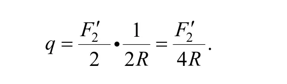
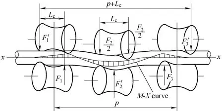
Fig. 1. Force analysis of traditional straightening force calculation system
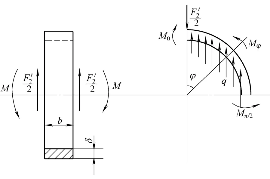
Fig. 2. Flattening force of tubes
The internal moment applied on the incision of the tube ring are M0and Mπ/2, respectively. The equation for the internal moment at angle? is

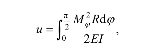
The elastic strain energy for the ring is
and the angular displacement at ?=0 is
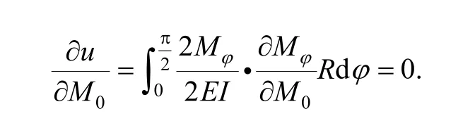
Therefore,
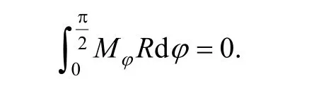
Substituting Mφin the equation, and we can obtain the following result:
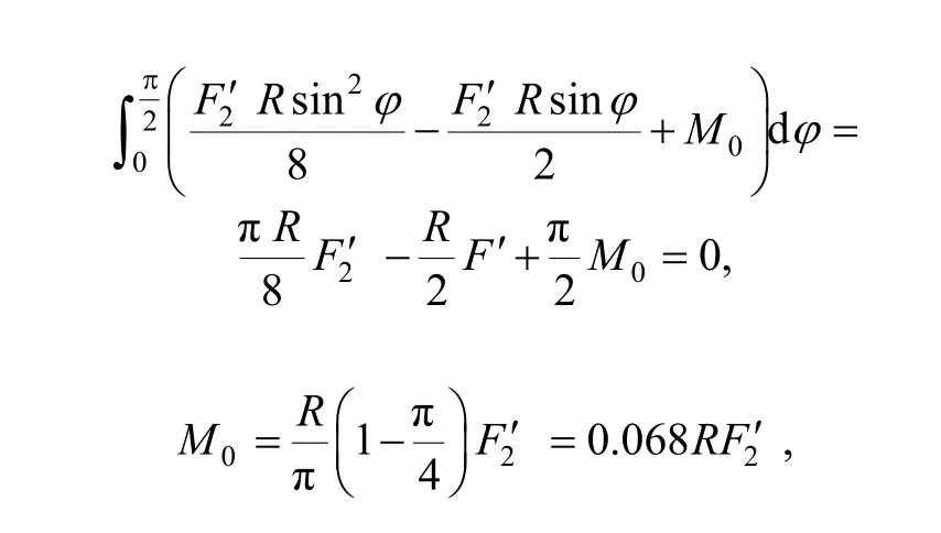
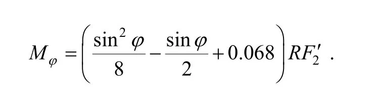
which is further substituted back to formula Mφ, and we can obtain
Substitute Mπ/2andsσ to the above formula and the maximum elastic flattening force is obtained:
The force applying on each roller was obtained from Fig. 1,which is expressed as follows:
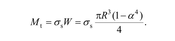
Where b is the contact length of the tube and the pressed roller 2′ (mm); R is the external radius of tube (mm);is the plastic bending ratio,=1.2–1.3 for the straightening tubes; Lcis the length of the contact area(mm),α is the inclination angle between the central line of the tube to be straightened and the axis of the straightening roller;sσ is the yield limit of the tube (MPa);p is the roller distance between rollers; Mtis the elastic limit bending moment for the tube (N·mm), and
3 New Calculating System for the Straightening Force
When the traditional straightening force calculating system was initially established, the shape for the straightening rollers was designed as hyperbola; therefore,the contact length between the tube and the straightening roller is small, which is only 0.1–0.2 times of the length of the roller. Therefore, when the pressing force applied to the tube by the upper and lower roller was analyzed, it was usually considered as centralized force. The new system for calculating the straightening force is bases on envelope method of the roller shape that was designed under the condition that the tube and the roller body are in ideally full contact, so that the contact length between the tube and the straightening roller is larger than 75% of the length of roller body regulated by national standard (JB/T 3163–1999 the Technical Condition for the Oblique Roller Tubes Straightening Machine). Therefore, the pressing force applied to the tube by the upper and lower roller can be considered as uniformly distributed force. The force analysis is shown in Fig. 3, which can be divided into two parts for consideration. One part is the bend straightening force (Fb1, Fb2and Fb3in Fig. 3) resulted from the pressing quantity (reverse bending quantity); another part is the flattening straightening force caused by the pressing force applied to the tube by the upper and lower roller. Due to the reverse bending quantity, the contact line between the roller and the tube at the middle is 1.5 times longer than that at both sides; therefore, the uniformly distributed forces for the upper and lower rollers at the middle and at the ends are Ftand Ft1, respectively. The resultant forces F of uniformly distributed force Ftor Ft1for the upper and lower rollers are equivalent in size and opposite in direction and act along the same line, therefore, they can counteract each other, and the shear force q does not exist. Hereinafter, the new calculating system for the straightening force is established based on the analysis of roller-shaped curve, flattening straightening force and bend straightening force.
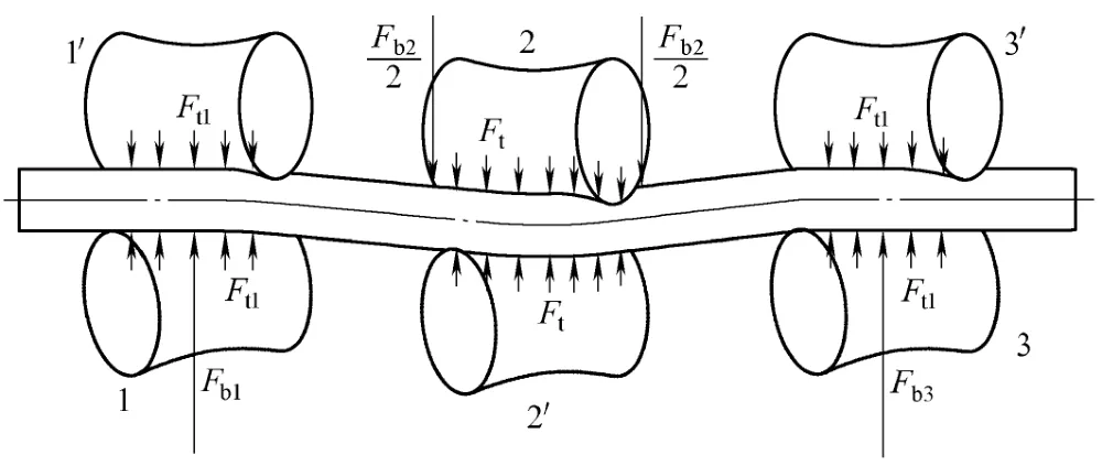
Fig. 3. Force analysis of the new system for calculating the straightening force
3.1 Roller shape curve
Roller shape curve of the oblique roller straightening machine is the key factor that influences the quality of the straightening[6]. Generally, the radius Rrat the thinnest part of the straightening roller, the length Lsof the straightening roller, and the fillet radius r of the end portion of the straightening roller are determined according to strength condition.
The envelope method is one of the major computing methods for the curve of the roller shape of the oblique roller straightening machine. The curve of the roller shape is considered to be constituted by the envelopes (common tangents) of an infinite number of spheres in this method.
The radius R' of the sphere is calculated according to the following formula:
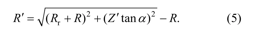
Where Rris the radius of the thinnest part of the straightening roller, R is the radius of the tube to be straightened, Z' is the distance between the center of the thinnest part of the straightening roller and the sphere center, and α is the angle between the center line of the tube to be straightened and the axial line of the straightening roller.
When Rris known, if Z' is given, the corresponding sphere radius R' could be calculated according to Eq. (5),the corresponding number of spheres and the envelopes of these spheres, namely the curve of the roller shape, could be drawn (as shown in Fig. 4). But the formula Rc= F(Z) of the curve of the roller shape has to be deduced in order to draw the figure accurately.
The radius Rcof the straightening roller that corresponds to coordinates Z is calculated by the following equation:
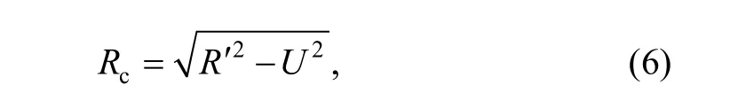
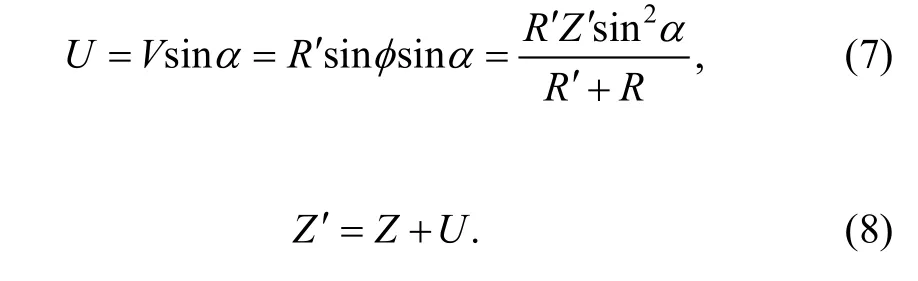
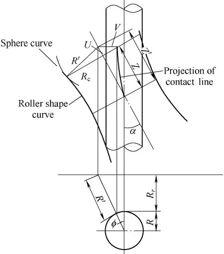
Fig. 4. Envelope method
Substitute Eqs. (7) and (8) into Eq. (6), we can obtain
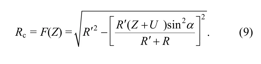
R' could be obtained from the given Z', Z and Rccould be obtained from U. The corresponding points Z and Rcare obtained by computer programming. As shown in Fig. 5,the curve of the roller shape, satisfying the practical requirements of engineering and with the ideally full contacting between the tube and the straightening roller,could be accurately drawn by inputting the coordinates of points Z, Rcinto the tabulated curve of SOLIDWORKS.This roller shape accords better with the practical curve of straightening, it could increase the contacting length between the tube to be straightened and the straightening roller, decrease the unit pressure on the contacting line,lighten the spiral indentation in the process of straightening,make the force distribution along the outer radius of the tube to be straightened more uniform, and provide necessary conditions for the straightening of high-precision tube with thin wall.
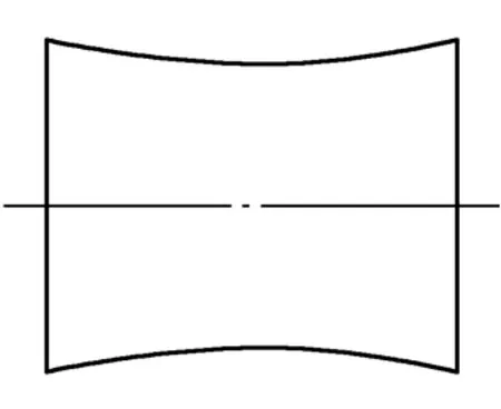
Fig. 5. Roller shape curve
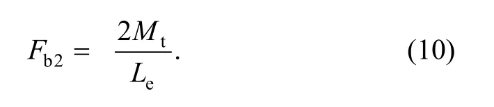
3.2 Bending straightening force
When the tube enters the straightening roller, on a part of the length, the tube is deformed by bending due to the press force applied by the roller contacted with it. With the spirally proceeding of the tube, the local bending of the tube is fully straightened in the scope that contacts the roller. When the tube is straightened, the upper roller at the middle of the straightening machine presses downwards to cause the tube to reverse bend downwards. Suppose the distance between the straightening rollers on both ends(that is to say, the support distance) is p, while the range p comprises elastic and plastic deformation areas. Generally speaking, the length of plastic deformation area is 30%–40% of p. The tube located in CA and BD area (Fig. 6)is in elastic deformation area. Therefore, it is not straightened. However, the stress at CD area reaches the yield limit, and causes plastic deformation to the tube there.Suppose the length of the elastic deformation area is Le.The bending moment of the plastic deformation is
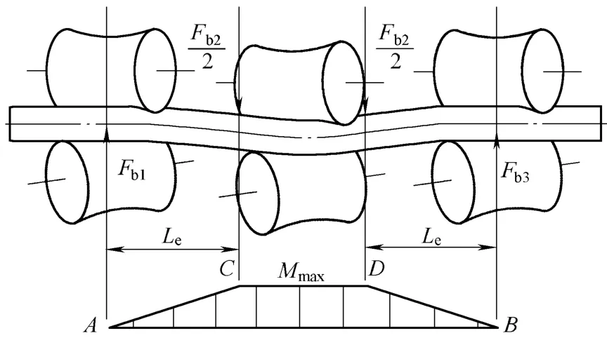
Fig. 6. Bending straightening analysis
3.3 Flattening straightening analysis
The elastic and plastic flattening deformations of the tube are generated when the tube being straightened enters the pair of rollers, together with the spiral movement of the tube, multiple repeated elastic and plastic flattening deformations in the two directions on the same cross section of the tube are formed, therefore the tube is straightened and rounded at the same time, which is the flattening straightening effect of six rollers straightening machine. The force status of the tube flattened and straightened by the pair of rollers is shown in Fig. 3 and Fig. 7. Ftor Ft1is uniformly distributed press force, that is the flattening force, and each resultant force is F.
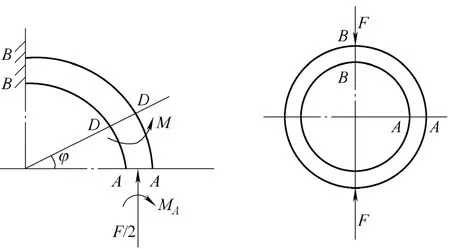
Fig. 7. Flattening straightening analysis
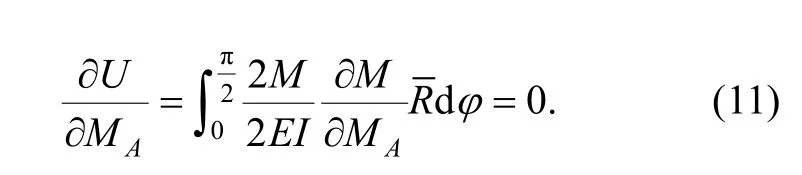
From the material mechanics point of view, the deformation of the tube can be considered as the deformation of the curved beam. Combined with the actual situation of the tube, the deformation energy of the 1/4 ring-formed curved beam can be represented as in Ref. [7]

Because of symmetry, the rotation angle of the A-A cross section of the tube is zero:
The inner torque at any position angle? is
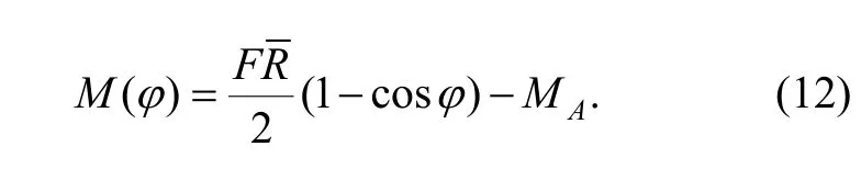
When we substitute Eq. (12) into Eq. (11), the bending moment MAon cross section A-A can be obtained:
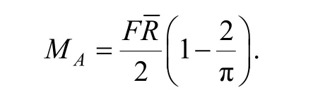
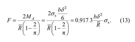
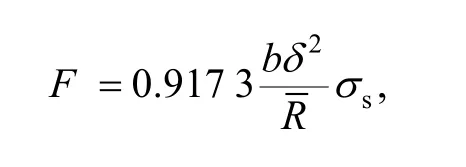
Considering that MB>MA, and the stress on the cross section B-B should exceed the yielding limit σs, in order to obtain the maximum flattening force, the stress on the cross section A-A is approximately considered as reaching the yielding limit σs, therefore, the flattening straightening force is obtained:
3.4 Combination of bending straightening and flattening straightening force
In the process of straightening, since the elastic and plastic bending condition can not be established at the two ends of the tube, the tube with hooks cannot be straightened only by the bending effect. While the six rollers straightening machine has both the bending and flattening straightening forces, the flattening effect is applied to the whole length; therefore, the six rollers straightening machine has good effect for straightening the tube.
Combination of the bending straightening force with the flattening straightening force is shown in Fig. 3, and the resultant force of the uniformly distributed flattening force Ftor Ft1is F. The force for each roller is F1, F1,′F2, F2′,F3,respectively, whose value can be represented as follows:

3.5 Calculating example
The material of the steel tube is GCr15, D=114 mm, δ= 6 mm, b=320 mm, Le=420 mm, p=1 240 mm,sσ=240 MPa,
(1) The flattening straightening force is calculated as
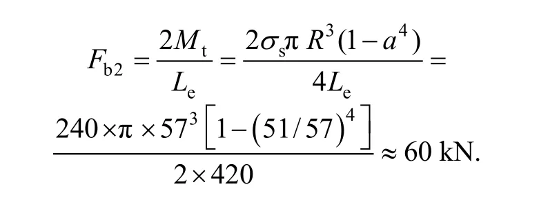
(2) The bending straightening force is calculated as
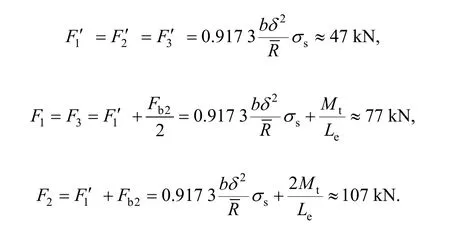
(3) The straightening force of each roller is calculated as
The straightening force of each roller actually measured is shown in Fig. 8. Therefore, the calculated result matches the actual measured result.
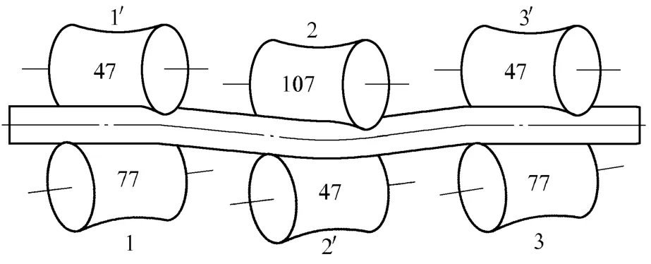
Fig. 8. Straightening force of each roller actually measured
3.6 Finite elements analysis
Finite elements analysis was carried out by using COSMOS for the process of flattening straightening of the steel tube on the oblique roller straightening machine[8].The material was selected according to the computing example: the model of finite elements was shown in Fig. 9.Solid units, analysis of static force and automatically divided grid were employed, and a flattening straightening force of 47 kN was applied uniformly along the spiral contacting line. The constraints are shown in Fig. 9. The result of the analysis of finite elements is shown in Fig. 10 and Fig. 11. Fig. 10 illustrates the regions reaching the yield limit under the effect of the straightening force, the unit of the yield limit in Fig. 10 is kg/cm2. Fig. 11 illustrates the enlarged figure of the stress distribution in longitudinal section. The analysis results in Fig. 10 and Fig. 11 accord with the analysis in section 2.3. The upper and lower sides of Fig. 11 are the distribution zone of tensile and compressive stress, respectively, the maximum stress is at the edge, the stress is smaller near the middle portion, and the center portion is neutral axis with no stress.
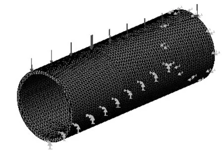
Fig. 9. Finite elements model for the process of flattening straightening of the steel tube
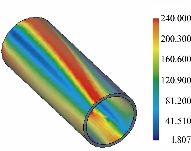
Fig. 10. Regions reaching the yield limit under the effect of the straightening force (MPa)
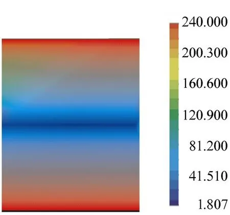
Fig. 11. Stress distribution in longitudinal section (MPa)
4 Comparison of Two Calculating Systems for Straightening Force
Because the traditional straightening force calculating system has calculated the shear force, and consideredtherefore, the result ( F2′)obtained in Eq. (1) is relatively smaller than the new straightening force obtained from the new calculating system. The force analysis in Fig. 1 is unreasonable, and is far from the actual force condition of the real roller system, and the force condition of each roller deduced therefrom deviates from the actual measured value. Table is the comparison of the traditional straightening force, the new straightening force and the actual measured value. F1, F2, F3in the traditional straightening force calculating system are 1.5–2 times bigger than those in the new straightening force calculating system, which causes the driving power of the straightening machine too big.
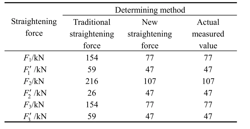
Table. Comparison of traditional straightening force,new straightening force and actual measured value
5 Conclusions
(1) The roller shape of the straightening roller, on which the new computing system for straightening force is based,was designed according to the envelope method under the condition of ideally full contacting between the tube and the straightening roller, guaranteeing the contact length between the tube and the straightening roller is larger than 75% of the length of the roller body regulated by the national standard—JB/T 3163–1999 the Technical Condition for the Oblique Roller Tubes Straightening Machine. Thus the pressing force generated upon the tube by the upper and lower rollers could be considered as uniformly distributed force.
(2) The force status of the traditional calculating system for the straightening force deviates far away from the actual force status of the roller system in the six-rollers straightening machine; therefore, its calculating result is far from the actual measured value. The force status of the new calculating system for the straightening force is reasonable,compared with the actual measured value, and its calculating accuracy satisfies the actual engineering requirement.
(3) The finite element analysis was carried out by using COSMOS for the process of flattening straightening of tube of the oblique roller straightening machine, and the correctness of the computation for flattening straightening force was testified.
(4) The effect of straightening of the six-rollers straightening machine depends on whether the adjustment of the three pairs of rollers could make the deformation of longitudinal bending and cross-sectional flattening enter the status of plastically deformation or not, thus the determination and monitor of the two kinds of straightening force has a decisive effect upon the performance of the straightening machine. The new six rollers straightening machine has already adopted the force sensor and computer and combined with the new calculating system for straightening force to realize the fully automatic adjustment of the straightening machine.
[1] MASIJILIEXUN A M. Tube straightening machine[M]. Beijing:China Machine Press, 1979.
[2] GAILAIKE W. The simple computing method for torque in oblique roller straightening machine[J]. Heavy Machinery, 1981(4): 53–57.
[3] CUI Pu. Straightening theory and parameter calculation[M]. Beijing:China Machine Press, 1987.
[4] LI Qiang, LI Jianwen. The analysis on straightening force computing system of six-rollers tube straightening machine[J]. Journal of Baotou University of Iron and Steel Technology, 1995, 14(1): 63-67.
[5] CUI Pu. Straightening theory and straightening machine[M]. 2nd ed.Beijing: China Machine Press, 2005.
[6] ZHOU Gaofeng, CAO Jujiang. Studying the mathematical model of the surface of cross-roller[J]. Journal of Shanxi University of Science& Technology, 2005, 23(3): 93-96.
[7] TIMOSHENKO S. Strength of materials — Part I elementary[M].3rd ed. New York: Van Nostrand Reinhold Company Ltd, 1978.
[8] SCHLEINZER G, FRANZ Dieter Fischer. Residual stresses in roller straightened rails[J]. Materials Science Forum, 2000, 347-349:368-373.
 Chinese Journal of Mechanical Engineering2010年1期
- Chinese Journal of Mechanical Engineering的其它文章
- Contents and Abstracts of Journal of Mechanical Engineering ISSN 0577-6686, CN 11-2187/TH*
- Measurement of Attenuation of Ultrasonic Propagating through the Thin Layer Media with Time Delay Spectrum
- Effect of Air Injector on the Performance of an Air-lift for Conveying River Sand
- Analysis and Optimization on Factors Affecting Forming Quality of Half Axle Gears Warm Precision Forging
- Numerical Method Based on Compatible Manifold Element for Thin Plate Bending
- Investigation on Uniaxial Tensile Instability of USIBOR1500 Steel Sheets at Elevated Temperature