
Numerical Investigation of Constructal Distributors with Different Configurations*
2009-05-14 06:23:14FANZhiwei范志偉ZHOUXinggui周興貴LUOLingai羅靈愛andYUANWeikang袁渭康
關(guān)鍵詞:范志
FAN Zhiwei (范志偉), ZHOU Xinggui (周興貴)**, LUO Ling’ai (羅靈愛) and YUAN Weikang (袁渭康)
?
Numerical Investigation of Constructal Distributors with Different Configurations*
FAN Zhiwei (范志偉)1,2, ZHOU Xinggui (周興貴)1,**, LUO Ling’ai (羅靈愛)2and YUAN Weikang (袁渭康)1
1State Key Laboratory of Chemical Engineering, East China University of Science and Technology, Shanghai 200237, China2Laboratoire Optimisation de la Conception et Ingénierie de l’Environnement, Université de Savoie, Savoie Technolac 73376, France
Seven distributors with different configurations are designed and optimized by constructal approach. Their flow distribution performance and energy dissipation are investigated and compared by computational fluid dynamics (CFD) simulation. The reliability of CFD simulation is verified by experiments on the distributor that has all distributing rectangle channels on a plate. The results show that the symmetry of the distributing channels has decisive influence on the performance of flow distribution. Increasing the generations of channel branching will improve the flow distribution uniformity, but on the other hand increase the energy dissipation. Among all the seven constructal distributors, the distributor that has dichotomy configuration, Y-type junctions and straight interconnecting channels, is recommended for its better flow distribution performance and less energy dissipation.
constructal distributor, configuration, flow distribution, energy dissipation
1 INTRODUCTION
For a number of fluidic devices in chemical process industry such as shell-tube heat exchangers, tubular reactors and static mixers,., flow distribution is always important because it has significant influences on their overall performance such as rate of mass or heat transfer, conversion or selectivity of reaction,[1, 2]. Flow maldistribution is generally caused by poor design and imprecise fabrication of the distributor, which will generally increase back-mixing and decrease the driving force of mass/heat transfer. When distributing a flow into parallel channels, the maximal flow rate ratio (ratio of the highest volume flow rate to the lowest one) could be as high as 4 if no measures have been taken for uniform flow distribution, as shown by Lalot[3]. Flow maldistribution with so high a maximal flow rate ratio would decrease the efficiency of a cross-flow heat exchanger by 25%. To homogenize the flow distribution, perforated baffles are frequently used. For example, Jiao et al. [4] introduced a perforated baffle into a plate-fin heat exchanger, which decreased the velocity ratio to 1.5. Zhang and Li [5] investigated a so-called two-stage- distribution header structure which has a perforated baffle between the two stages using FLUENT,the numerical prediction was in line with the experimental results, which show that the two-stage design could improve the flow distribution performance. Wen. [6, 7] showed that installing a punched baffle into the header of plate-fin heat exchanger would enhanced the heat exchanger efficiency about 12%.
Introducing a flow distributor for uniform flow distribution will undoubtedly increase flow resistance. Therefore, minimizing energy dissipation emerges as an important goal of distributor design. The constructal distributors, which have a branched multiscale structure, have handsomely solved the problem of minimizing energy dissipation for uniform flow distribution. Different constructal distributors with different configurations have been proposed in the literature [8-10], which can be fabricated by stereolithography with epoxy resin or metal powder. However, because the 3-dimensional constructal flow distributors are costly to fabricate, only a few were really fabricated and evaluated [11, 12].
Numerical prediction provides a cheap means to evaluate the performance of the distributor, and moreover, it avoids the problem of imprecise fabrication that may interfere with the observation and lead to wrong conclusion. In this paper, a comparison of different configurations on the performance of flow distribution is conducted by computational fluid dynamics (CFD), in an attempt to provide guideline for the design of the constructal distributor.
2 CONFIGURATIONS OF CONSTRUCTAL DI- STRIBUTOR
Figure 1 shows the seven constructal distributors to be investigated, which are different from each other by the furcation pattern (bi-furcation or tetra-furcation), the junction type (T-type or Y-type) and the interconnecting channel shape (straight line or arc). Table 1 summarizes the configurations. These distributors are expected to distribute a fluid into sixteen outlets uniformly located in a 30 mm×30 mm square. Pro and P-2 have the same configurations except that the cross section of the interconnecting channels is rectangle for Pro and circle for P-2.
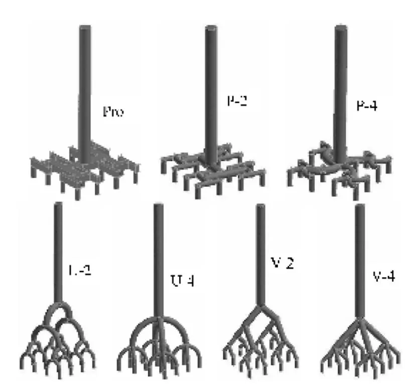
Figure 1 Schematic view of the constructal distributors
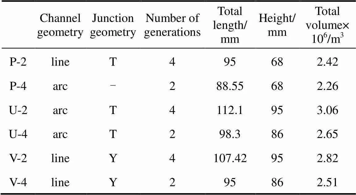
Table 1 Configuration of the constructal distributors
For U-2 and U-4, all the branches have an arc angle of π/2; while for V-2 and V-4, all the branches have an angle of π/4 with the vertical. The length of the inlet is set as 60 mm to diminish the entrance effect.
The dimensions of the channels are optimized with the goals of minimum energy dissipation and minimum total pore volume. Based on the assumption of established laminar Poiseuille flow, the following mathematic equations, which are referred to as Murray’s Law, are applied:
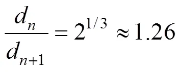
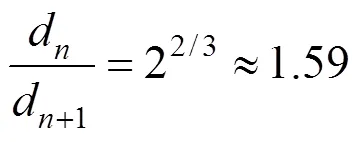
Here,dis the diameter of the channels of generation. The dimension of Pro is determined according to Ref. [13],
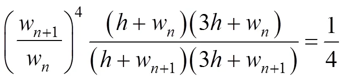
whereandware the height and width of the channels. Tables 2 and 3 summarize the optimized dimensions for all the distributors.
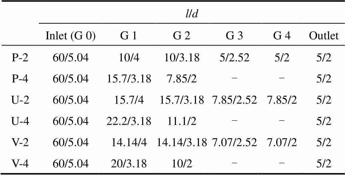
Table 2 Dimensions of the constructal distributors
Note:stands for the length,for the diameter, G is the abbreviation of ‘generation’.
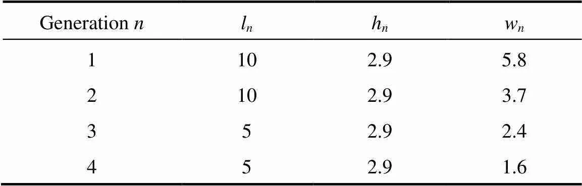
Table 3 Dimensions of the bifurcation channels of Pro (mm)
3 SIMULATIONS
The geometries of the constructal distributors are constructed with Gambit?according to the geometry parameters presented in Tables 1, 2 and 3. Composite constructive grids are applied to mesh the computational projects, and the number of the involved cells ranges from 250000 to 300000 respectively. Smooth transition is introduced at the junctions and channel turns.
By assuming that the channel surface is smooth, the fluid is incompressible Newtonian and the flow pattern is stable, the flow in the channels of the distributors are simulated by a commercial code Fluent 6.0 with water as the working fluid. The standard-model is adopted and the non-equilibrium wall function is chosen for near-wall treatment. The finite volume method is used for the solution of the Navier-Stokes equations. To improve the convergence that is limited by pressure-velocity coupling, the semi-implicit SIMPLEC method is used and the second order upwind differential scheme is employed to approximate the convective terms.
In the simulation, only the inlet is defined as the velocity-inlet and the velocity is given as input. All the sixteen outlets are defined as pressure-outlet, and the gauge pressure is set zero. On all solid surfaces, the no-slip wall boundary condition is imposed. The solution is considered to converge when the sum of the normalized residuals for each control equation is on the order of 1′10-5. Grid independence is guaranteed by using finer grids until the simulation results are hardly affected.
4 RESULTS AND DISCUSSION
First, to verify the reliability of the simulation, distributor Pro is fabricated by electric spark cutting and precise machining, and fluid dynamics experiments are carried out with water as the test fluid to evaluate the uniformity of flow distributionand the energy dissipation. Here,is the Reynolds number defined at each individual outlet, andis the ratio of the highest flow rate to the lowest one of the sixteen outlets, which is used as the criterion of flow distribution performance, the smaller the maximal flow rate ratio, the better the flow distribution performance. Fig. 2 shows that the uniformity of flow distribution and pressure drop determined by simulation coincide very well with the experiments, the maximal deviation being 3.32% for the maximal flow rate ratio, and 0.6% for the pressure drop. This justifies the computational fluid dynamics model and the numerical procedure for the simulation.
Figure 2 Comparison of experimental results and numerical prediction of Pro
●?experimental results; ——?numerical prediction
Figure 3 shows the uniformity of flow distribution and the pressure drop as functions of averagedat outlets for all the seven distributors. Fig. 4 shows directly the flow rates at the sixteen outlets of U-2 and V-2 at an averaged outletof 2030. The U-type distributors have the best performance in uniformly distributing the fluid while the V-type ones have the smallest pressure drop. Among all the seven distributors, V-4 and P-4 have the worse performance in distributing the fluid. Anatomizing the structures of the distributors, one can see that this is because of the asymmetry of the channel structures of V-4 and P-4, in which the inertia of the outflow from the mother channels directly influences the flow in the child channels.

Figure 3 Flow distribution performance of the constructal distributors
●?U-2;○?U-4;▼?V-2; △?V-4; ■?P-2; □?P-4; ◆?Pro

Figure 4 Non-uniformity of U-2 and V-2 at an averaged outletof 2030
For the same furcation patterns, comparing U-2 and V-2, or U-4 and V-4, one can see that U-type distributors general consume more energy than V-type ones. U-2 and P-2 consume more energy than V-2, and U-4 consumes more energy than V-4. The main reason is that the T-junctions of U-2, P-2 and U-4 consume more energy than the Y-junctions of V-2 and V-4. For the distributors, for example, U-2 and U-4, and V-2 and V-4, which have the same type of interconnecting channels, one can see that the tetra-furcation pattern costs less energy than does the bi-furcation pattern. This is because that the configuration with tetra-furcation pattern has less number of junctions. These discussions imply that the pressure drop of a distributor is mainly caused by the junctions.
P-2 and Pro have almost the same uniformity of flow distribution as they have the same bifurcation pattern, junction type, and channel geometry. But their pressure drops are quite different. The difference between both of them is that the channels are rectangle for Pro and round for P-2. Moreover, from Table 4 one can see that, as the result of different design procedures, the equivalent diameters of the rectangle channels in Pro are different from the diameters of the round channels in P-2, and the cross section areas of the channels in Pro are larger than that in P-2, which account for the smaller pressure drop of Pro.
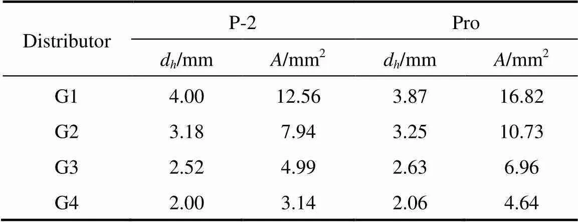
Table 4 Comparison of the geometry dimension of P-2 and Pro
NOMENCLATURE
cross section area of interconnecting channels, mm2
dequivalent diameter, mm
ddiameter of the channels, mm
hheight of the channels, mm
llength of the channels, mm
Reynolds number
wwidth of the channels, mm
maximal flow rate/velocity ratio
Subscripts
number of generation
1 Chiou, J.P., “Thermal performance deterioration in crossflow heat exchanger due to the flow nonuniformity”,., 100, 580-587 (1978).
2 Shah, R.K., London, A.L., “Effects of nonuniform passages on compact heat exchanger performance”,.., 102, 653-659 (1980).
3 Lalot, S., Florent, P., Lang, S.K., Bergles, A.E., “Flow maldistribution in heat exchangers”,..., 19 (8), 847-863 (1999).
4 Jiao, A., Zhang, R., Jeong, S.K., “Experimental investigation of header configuration on flow maldistribution in plate-fin heat exchanger”,..., 23 (10), 1235-1246 (2003).
5 Zhang, Z., Li, Y.Z., “CFD simulation on inlet configuration of plate-fin heat exchanger”,, 43 (12), 673-678 (2003).
6 Wen, J., Li, Y.Z., “Study of flow distribution and its improvement on the header of plate-fin heat exchanger”,, 44 (11), 823-831 (2004).
7 Wen, J., Li, Y.Z., Zhou, A.M., Zhang, K., “An experimental and numerical investigation of flow patterns in the entrance of plate-fin heat exchanger”,.., 49 (9/0), 1667-1678 (2006).
8 Tondeur, D., Luo, L.A., “Design and scaling laws of ramified fluid distributors by the constructal approach”,..., 59 (8/9), 1799-1813 (2004).
9 Luo, L.A., Tondeur, D., “Optimal distribution of viscous dissipation in a multi-scale branched fluid distributor”,...., 44 (12), 1131-1141 (2005).
10 Luo, L.A., Tondeur, D., “Multiscale optimisation of flow distribution by constructal approach”,., 3, 329-336 (2005).
11 Luo, L.A., Fan, Y.L., Zhang, W.W., Yuan, X.G., Midoux, N., “Integration of constructal distributors to a mini crossflow heat exchanger and their assembly configuration optimization”,..., 62 (13), 3605-3619 (2007).
12 Luo, L.A., Fan, Z.W., Le Gall, H., Zhou, X.G., Yuan, W.K., “Experimental study of constructal distributor for flow equidistribution in a mini crossflow heat exchanger (MCHE)”,..., 47 (2), 229-236 (2008).
13 Fan, Z.W., Zhou, X.G., Luo, L.A., Yuan, W.K., “Experimental investigation of the flow distribution of a 2-dimensional constructal distributor”,..., 33 (1), 77-83 (2008).
2008-06-19,
2008-09-24.
the National Natural Science Foundation of China (20476026), the Program for New Century Excellent Talents in University (05-0416), the Creative Team Development Project of Ministry of Education (IRT0721), and the 111 Project of Ministry of Education and State Administration of Foreign Experts Affairs (B08021).
** To whom correspondence should be addressed. E-mail: xgzhou@ecust.edu.cn
猜你喜歡
職工法律天地·上半月(2022年5期)2022-06-29 22:02:51
——淺談新課標(biāo)新高考下二輪復(fù)習(xí)策略
教學(xué)考試(高考化學(xué))(2022年2期)2022-05-09 14:20:02
Chinese Physics B(2021年11期)2021-11-23 07:30:22
Plasma Science and Technology(2021年3期)2021-03-22 08:04:24
Chinese Physics B(2021年1期)2021-01-21 02:07:22
婦女生活(2020年1期)2020-02-16 14:43:37
藝術(shù)家(2017年1期)2017-11-29 17:11:16
女性天地(2017年1期)2017-04-21 11:45:26
37°女人(2016年2期)2016-09-25 10:21:26
37°女人(2016年2期)2016-02-19 19:42:27
 Chinese Journal of Chemical Engineering2009年1期
- Chinese Journal of Chemical Engineering的其它文章
- An Improved Fuzzy Predictive Control Algorithm and Its Application to an Industrial CSTR Process*
- Preparation, Characterization and Catalytic Behavior of 12-Molybdophosphoric Acid Encapsulated in the Supercage of Cs+-exchanged Y Zeolite*
- Purification of Sulfuric and Hydriodic Acids Phases in the Iodine-sulfur Process*
- Synthesis and Characterization of Novel Temperature and pH Responsive Hydroxylpropyl Cellulose-based Graft Copolymers
- The Separation of Catechol from Carbofuran Phenol by Extractive Distillation*
- Electrochemical Performance of Nickel Hydroxide/Activated Carbon Supercapacitors Using a Modified Polyvinyl Alcohol Based Alkaline Polymer Electrolyte*